Geosynthetic tufted drain barrier

a technology of tufted drain and drain barrier, which is applied in the field of geosynthetic tufted drain barrier, can solve the problems of destabilizing the system, affecting the proper design of geosynthetically-lined structures, and affecting the egress of undesirable fluids, so as to achieve the effect of egressing undesirable fluids in tim

Active Publication Date: 2012-08-14
TURF SERVICES
View PDF13 Cites 23 Cited by
  • Summary
  • Abstract
  • Description
  • Claims
  • Application Information

AI Technical Summary

Benefits of technology

[0021]It is also an object of the invention to provide a GTDB that is laminated to a gas transmissive element, integrating an upper surface of synthetic turf to high transmissive geonet cores to permit the timely egress of undesirable fluids or gases.

Problems solved by technology

For safety, improved performance and durability, and longevity, a number of limitations are placed upon the proper design of geosynthetically-lined structures.
As a result, cover soils are subject to forces that destabilize the system.
In fact, erosion is usually a major source of damage to man-made, as well as natural slopes.
When storms, high winds, or precipitation occur, seepage forces are introduced into the cover soils overlying the geomembranes; slope failures can occur.
These limitations included the ability to construct slopes at steep inclination angles.
Drainage geocomposites also have numerous limitations.
For example, while drainage geocomposites may provide great speed at conveying fluids, they conversely lack any meaningful storage capacity as a result of their nominal thickness, typically less than 0.50 inches (1.27 cm).
If a drainage geocomposite clogs or is improperly sized, the overlying soil becomes saturated.
Saturated soils lose internal shear strength and cohesion and are subjected to seepage-induced forces resulting in massive slope failures.
Drainage geocomposites are also susceptible to biological clogging.
In fact, there are occasions when vegetative soil cover roots entirely clog geosynthetic drainage systems.
Moreover, drainage geocomposites are susceptible to exposure to UV light.
Uniformly graded sand, stone, and recycled materials lack cohesion.
A lack of cohesiveness places significant limits on the slope inclination angle for natural or recycled drainage systems.

Method used


Image

  • Geosynthetic tufted drain barrier
  • Geosynthetic tufted drain barrier
  • Geosynthetic tufted drain barrier

Examples


Embodiment Construction

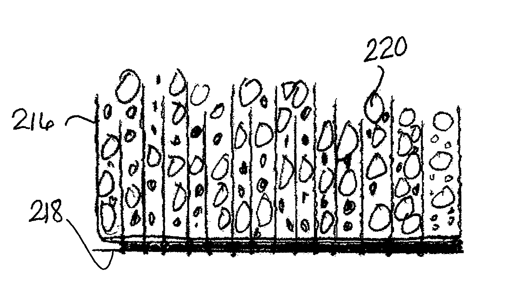
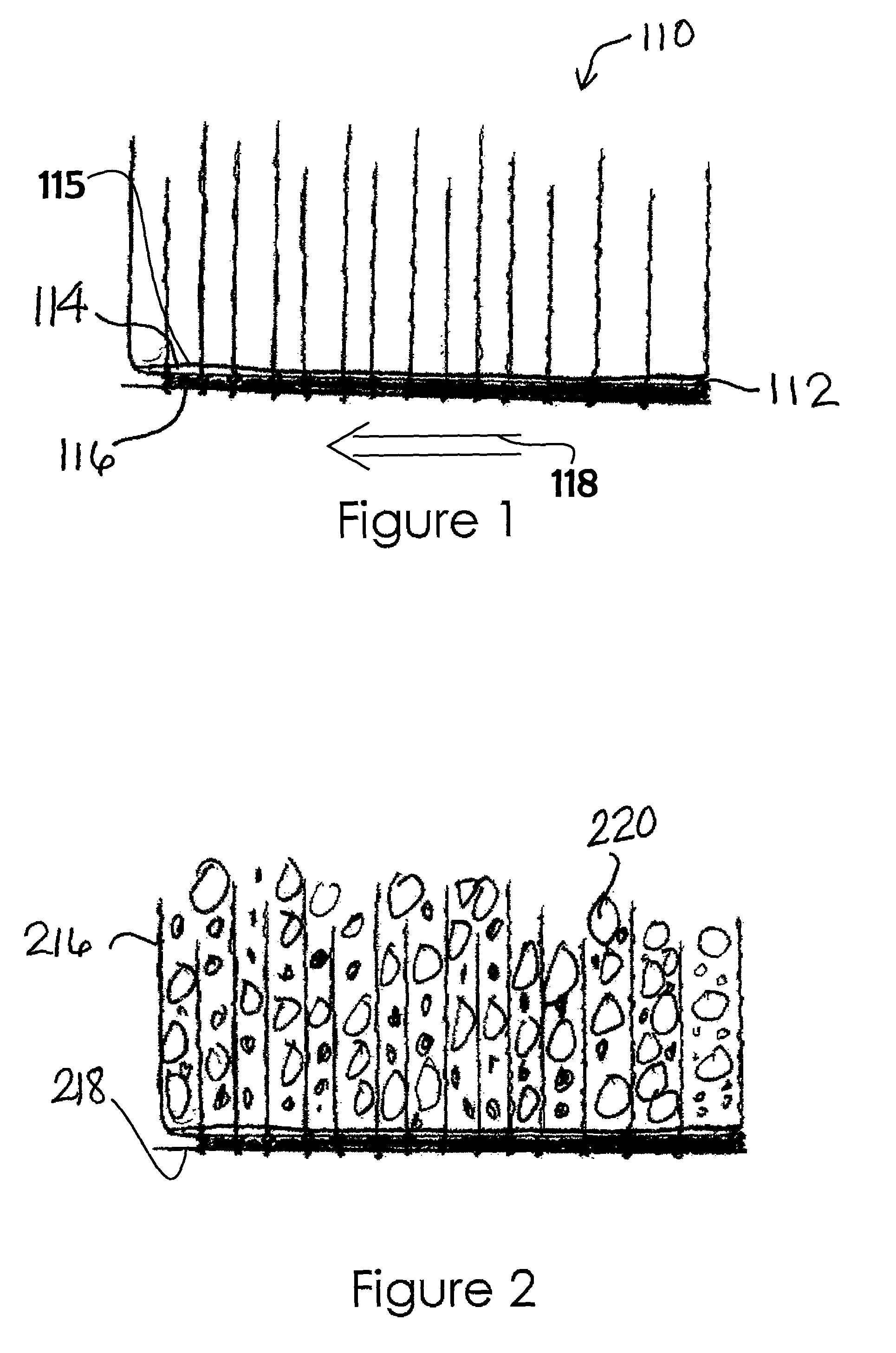
[0033]The present invention is a geosynthetic tufted drain barrier for preventing vertical migration of fluids. On a membrane is disposed a substantially impermeable layer or anchor backing. The substantially impermeable layer can be woven or non-woven. A plurality of tufted tensile elements is attached and forms a part of the substantially impermeable layer in aligned or offset rows. Infill material chosen from the group: sand, stone, rubber, slag, recycled concrete, recycled glass, and expansive minerals, or combinations thereof can be introduced to the tufted tensile elements. The structure consists of combining a liner, vertical or tufted tensile elements, and a natural or recycled uniformly graded, granular-based drainage system to allow for surface water collection and removal while maintaining slope stability of the drainage layer.

[0034]Referring now to FIG. 1, there is shown a GTDB 110 of the invention. Liner 112 consists of a substantially impermeable layer 114 having upper...


PUM


Abstract

A geosynthetic tufted drain barrier (GTDB) for preventing vertical migration of fluids. On a substantially impermeable woven or non-woven continuous layer is disposed a membrane. The tensile strength of the impermeable layer is at least 5 lbs/lineal ft (3.0 kg/lineal m). The permeability of the membrane is no greater than 10−4 cm/sec. Tufted tensile elements are attached to the membrane, each one being attached to the membrane at a density of at least 25 tufted tensile elements per square foot (30 square cm). The tufted tensile elements are formed in rows and are disposed at a density of at least four rows per square foot (30 square cm). Infill material can be introduced to the tufted tensile elements. The drain barrier may be constructed with integrated letters, logos, and signage and one or more colors.

Description

FIELD OF THE INVENTION[0001]The present invention relates to geosynthetic tufted drain barriers (GTDBs) and, more particularly, to a GTDB having a filler material constrained by tufted tensile elements having particular height to prevent infill loss and in which the GTDB can drain surface fluids while resisting erosive forces.BACKGROUND OF THE INVENTION[0002]Synthetic turf systems, as alternatives to natural grass surfaces, are well known. They represent an improvement over natural grass in some respects, resisting wear and severe weather and typically requiring less maintenance. Prior art synthetic turf systems, sold under trademarks such as Field Turf, Sprint Turf, and Sportex, include a synthetic playing surface often coupled with infill materials.[0003]Artificial grass is used as a covering for everything from landfills to playing fields to airport runways to landscaping to property subject to mudslides and landslides. Geosynthetically-lined slopes are also common. The liners ar...

Claims


Application Information

Patent Timeline
Patent Type & Authority Patents(United States)
IPC IPC(8): E02D17/20
CPCE02D17/202
Inventor RHOADES, CHARLESIANNIELLO, PETER J.
Owner TURF SERVICES
Why Eureka
Try Eureka