Massage Device

A technology of clamping mechanism and moving mechanism, which is applied in the direction of roller massage, kneading massage equipment, massage auxiliary products, etc., can solve the problems of single massage feeling and lack of change, and achieve the effect of comfortable massage feeling

Active Publication Date: 2012-02-01
DAITO ELECTRIC MACHINE IND
View PDF9 Cites 19 Cited by
  • Summary
  • Abstract
  • Description
  • Claims
  • Application Information

AI Technical Summary

Problems solved by technology

Therefore, the resulting massage s...

Method used


Image

  • Massage Device
  • Massage Device
  • Massage Device

Examples


no. 1 approach

[0050] Figure 1 to Figure 13 The first embodiment of the massage machine of the present invention is shown.

[0051] The massage machine 1 according to the first embodiment is configured to target the left and right legs of the user, and simultaneously perform pinch massage and linearly moving finger pressure on both the lower leg L and the foot F constituting the legs. massage.

[0052] In addition, in this specification, "lower leg part L" means the part located below the knee and higher than the ankle part among human legs, and "foot part F" means the part lower than the ankle part. and, figure 1 and figure 2 The direction indicated by the arrow line X is called the front-rear direction, the direction indicated by the arrow line Y is called the left-right direction (width direction), and the direction indicated by the arrow line Z is called the up-down direction.

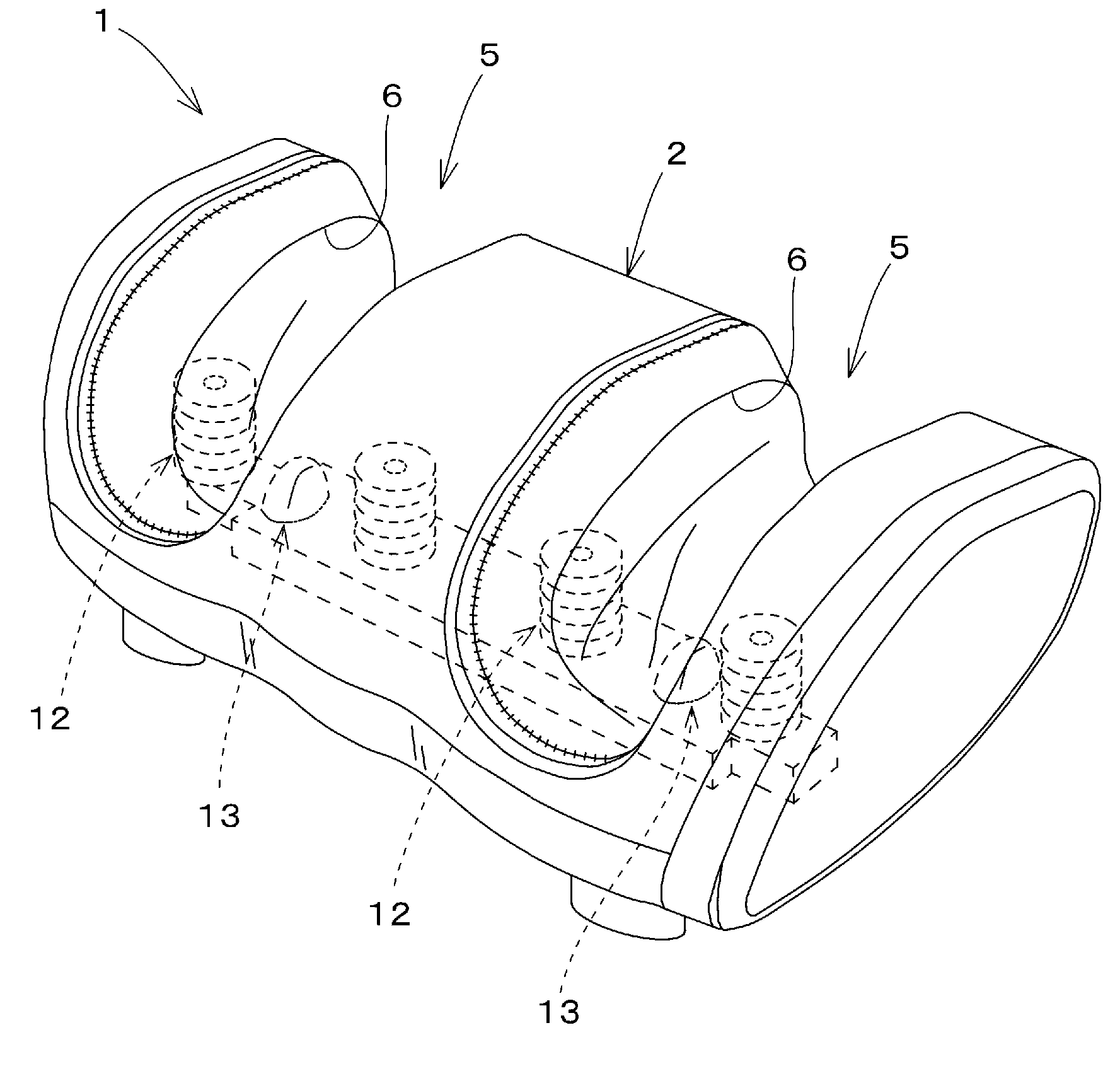
[0053] Such as figure 2 As shown, the massage machine 1 of the first embodiment has a housing 2 that i...

no. 2 approach

[0157] Figure 14 The second embodiment of the massage machine of the present invention is shown.

[0158] The massage machine 1 of the second embodiment is constituted as a massage machine dedicated to feet or a massage machine dedicated to shanks, and only has a horizontal horizontal pressure massage mechanism 12 and a horizontal back pressure massage mechanism 13 (not equipped with a vertical horizontal pressure massage mechanism 10 and a horizontal pressure massage mechanism 13). Vertical back pressure massage mechanism 11). This massage machine is very compact, which is very useful as a massage machine that responds to the user's needs.

[0159] Other configurations, effects, usage conditions, and the like are substantially the same as those of the first embodiment, and thus detailed description thereof will be omitted below. In addition, the same code|symbol is attached|subjected to the structure substantially the same as 1st Embodiment.


PUM


Abstract

Provided is a massage device that can provide a massage in which shiatsu pressure points are moved linearly over a wide range, in the long direction of the body, thereby providing a fresh and comfortable massage experience. The provided massage device (1) has: a pair of massage members (23, 24) that are disposed opposite each other at a separation so that a part of the body can be inserted therebetween; a clamping mechanism (162) that moves one or both of the massage members (23, 24) in the width direction of the body inserted between the pair of massage members, thereby clamping and applying pressure to the body; and a movement mechanism (26) that moves the massage members (23, 24) in the long direction of the body while maintaining the clamp state of the massage members (23, 24) due to the clamping mechanism (162).

Description

technical field [0001] The invention relates to a massage machine. Background technique [0002] Conventionally, a massage machine applied to a footrest of a chair-type massage device is known as a massage machine capable of massaging a leg (particularly from below the knee to around the ankle) (for example, Patent Document 1). This massage machine includes a pair of left and right treatment recesses, and airbags are respectively provided on inner surfaces of both side walls and both side surfaces of an intermediate wall of the treatment recesses. By inflating and contracting each of these airbags by the air supply and discharge device, it is possible to simultaneously massage both legs fitted into the respective treatment recesses. [0003] In general, the central portion of the airbag swells the most, and the swells become smaller as it goes toward both ends. Therefore, a sufficient pressing force may be obtained only in a narrow range in the longitudinal direction of the...

Claims


Application Information

Patent Timeline
IPC IPC(8): A61H7/00
CPCA61H2205/12A61H2015/0014A61H2205/106A61H2201/1669A61H2201/1676A61H15/0078A61H7/00A61H15/00A61H39/04
Inventor 石川哲也野田茂树清水新策
Owner DAITO ELECTRIC MACHINE IND
Why Eureka
Try Eureka