Drying device and film producing method from solution

A drying device and solution film-making technology, which are applied to flat products, coatings, household appliances, etc., can solve the problem of uniform suction of difficult-to-dry wind, unstable optical properties in the width direction, and uneven drying conditions in the width direction of the cast film. Stability and other problems, to achieve the effect of suppressing the deviation of optical characteristics

Active Publication Date: 2012-02-08
FUJIFILM CORP
View PDF5 Cites 6 Cited by
  • Summary
  • Abstract
  • Description
  • Claims
  • Application Information

AI Technical Summary

Problems solved by technology

However, since the suction port 202b is extended, it is difficult to make the suction amount of the drying air uniform in the width direction.
Therefore, resulting in unstable drying conditions in the width direction of the cast film
The optical film subjected to the drying process under such conditions causes the optical characteristics (such as Re, Rth) to be unstable in the width direction

Method used


Image

  • Drying device and film producing method from solution
  • Drying device and film producing method from solution
  • Drying device and film producing method from solution

Examples


Embodiment

[0116] (experiment 1)

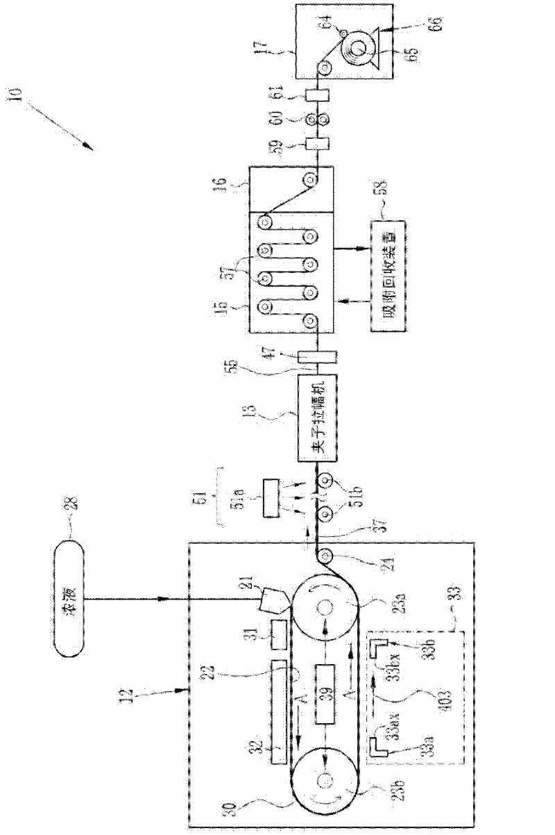
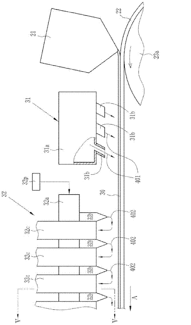
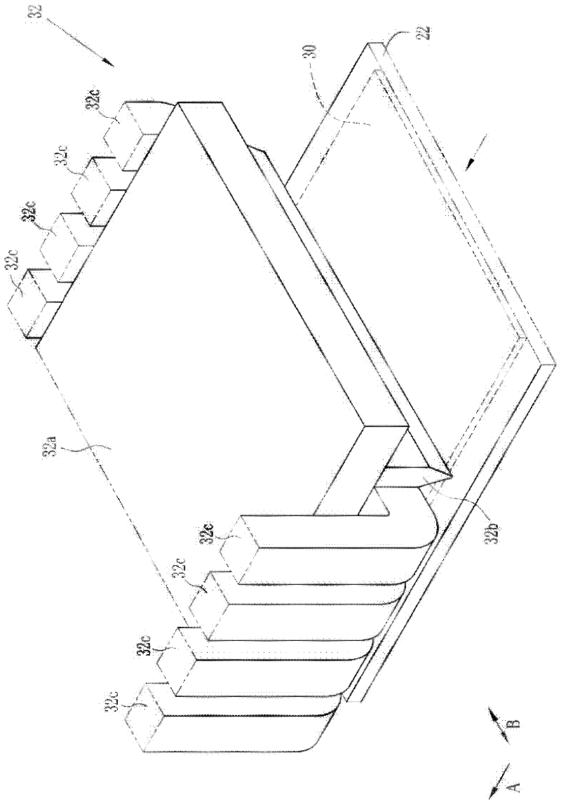
[0117] exist figure 1 In the solution film forming apparatus 10 shown, a film 55 is formed. In the casting chamber 12 , the dope is cast on the casting belt 22 using the casting die 21 , and the casting film 30 is formed on the casting belt 22 . The casting width at this time was 1800 mm. Thereafter, the casting film 30 was dried by the first to third drying units 31 to 33 . The interval of the air supply slits 32bx on the A direction is 5mm, and the length L1 of the air supply slits 32bx on the B direction (reference Figure 5 ) is 1800mm, CL1 (reference Figure 9 ) is 150mm, CL2 (reference Figure 9 ) is 150mm. And the 2nd drying air 402 of 50 degreeC temperature was sprayed from the nozzle 32b at the air velocity of 20 m / sec.

[0118] (experiment 2)

[0119] The film 55 was produced in the same manner as in Experiment 1 except that CL1 was set to 250 mm.

[0120] (Experiment 3)

[0121] The film 55 was produced in the same manner as in Exp...


PUM

PropertyMeasurementUnit
widthaaaaaaaaaa
widthaaaaaaaaaa
widthaaaaaaaaaa

Abstract

Provided are a drying device and a film producing method from solution. A second drying unit for drying a curtain coating film (30) comprises a case-like feeding pipe, vertical nozzles (32b) venting drying wind (402), and suction pipes (32c) sucking drying wind (402). A feeding pipe is arranged at the upside of the curtain coating film (30). The vertical nozzles (32b), from the bottom of the feeding pipe, protrude toward the curtain coating film (30). The suction pipes (32c) are arranged at both sides of the B direction of the vertical nozzles (32) which are arranged along the direction toward the A direction. The suction pipes (32c) are provided with suction ports (32cx) for sucking the drying wind (402). The suction ports (32cx) are arranged at the position farther away from the curtain coating film (30) than the blowing-in slots (32bx) arranged upon the vertical nozzles (32b). A suction path is formed among the vertical nozzles (32b).

Description

technical field [0001] The invention relates to a drying device and a solution film forming method. Background technique [0002] A light-transmitting polymer film (hereinafter, referred to as a film) is widely used as an optical film because it is light in weight and easy to mold. Among them, cellulose ester-based films such as cellulose acylate are used for optical films (for example, retardation films, polarizing plate protective films, etc.) ). [0003] Such membranes are produced by solution membrane-forming methods. The outline of the solution film forming method is as follows. First, a polymer solution (hereinafter referred to as a dope) containing a polymer and a solvent is made to flow, and a cast film is formed on a support. Second, the solvent is evaporated from the cast film until the cast film is in a state where it can be transported independently. 3. Peel off the cast film from the support as a wet film. Thereafter, a film can be obtained from the wet fi...

Claims


Application Information

Patent Timeline
Patent Type & Authority Applications(China)
IPC IPC(8): C08J5/18
CPCB29C41/28B29C41/34B29C41/46B29C41/52B29D11/00788B29L2007/00B29L2011/00B29L2031/7644
Inventor 吉田俊一加藤仁
Owner FUJIFILM CORP
Why Eureka
Try Eureka