Electronic equipment

A technology for electronic equipment and setting parts, which can be applied to TVs, electrical components, color TVs, etc., and can solve problems such as increasing the burden of operation

Inactive Publication Date: 2012-02-08
SANYO ELECTRIC CO LTD
View PDF4 Cites 9 Cited by
  • Summary
  • Abstract
  • Description
  • Claims
  • Application Information

AI Technical Summary

Problems solved by technology

This increases the burden of operation, so a simpler operation method is expected

Method used


Image

  • Electronic equipment
  • Electronic equipment
  • Electronic equipment

Examples


no. 1 Embodiment approach

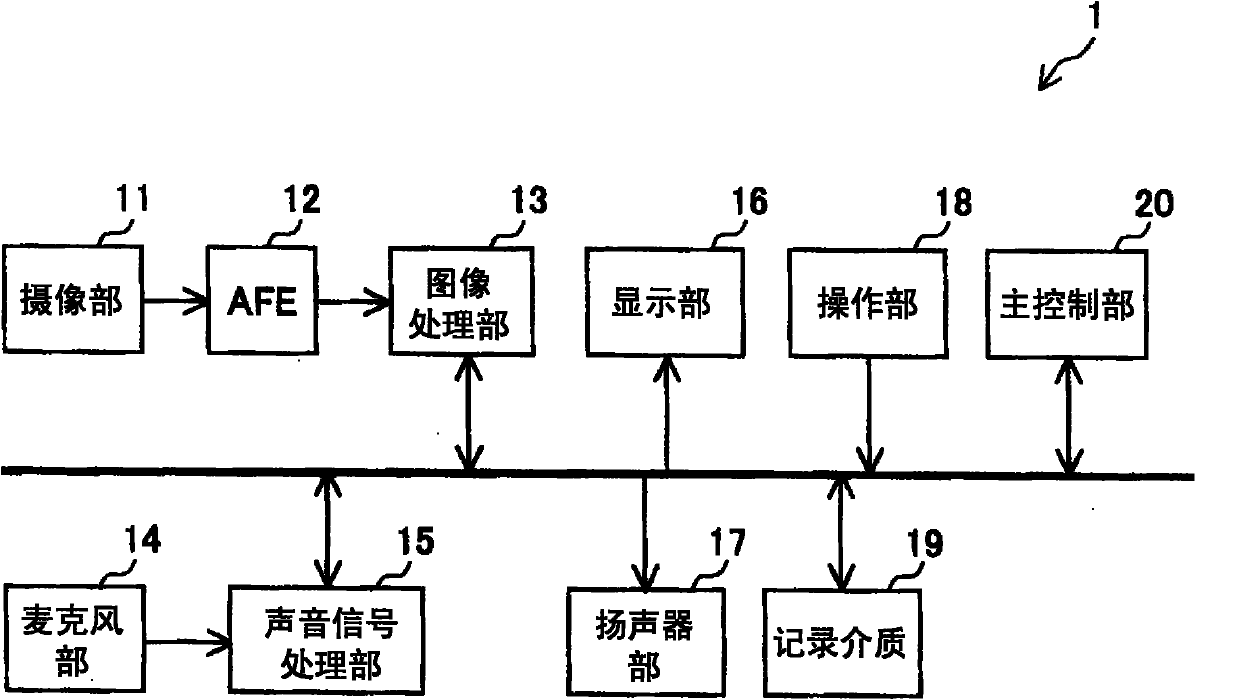
[0047] The first embodiment of the present invention will be described. figure 1 It is a schematic overall block diagram of the imaging device 1 according to the first embodiment. The imaging device 1 is a digital still camera capable of photographing and recording still images, or a digital video camera capable of photographing and recording of still images and moving images. The imaging device 1 may be a device mounted on a mobile terminal such as a mobile phone.

[0048] The imaging device 1 includes an imaging unit 11 , an AFE 12 , an image processing unit 13 , a microphone unit 14 , an audio signal processing unit 15 , a display unit 16 , a speaker unit 17 , an operation unit 18 , a recording medium 19 and a main control unit 20 .

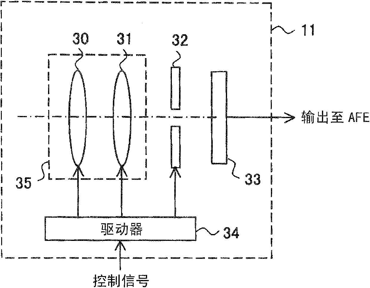
[0049] figure 2An internal configuration diagram of the imaging unit 11 is shown. The imaging unit 11 has an optical system 35 , an aperture 32 , an imaging element 33 composed of a CCD (Charge Coupled Device) or a CMOS (Complementary Met...

no. 2 Embodiment approach

[0104] A second embodiment of the present invention will be described. The second embodiment is an embodiment based on the first embodiment, and matters not particularly described in the second embodiment are applicable to the second embodiment as long as there is no contradiction.

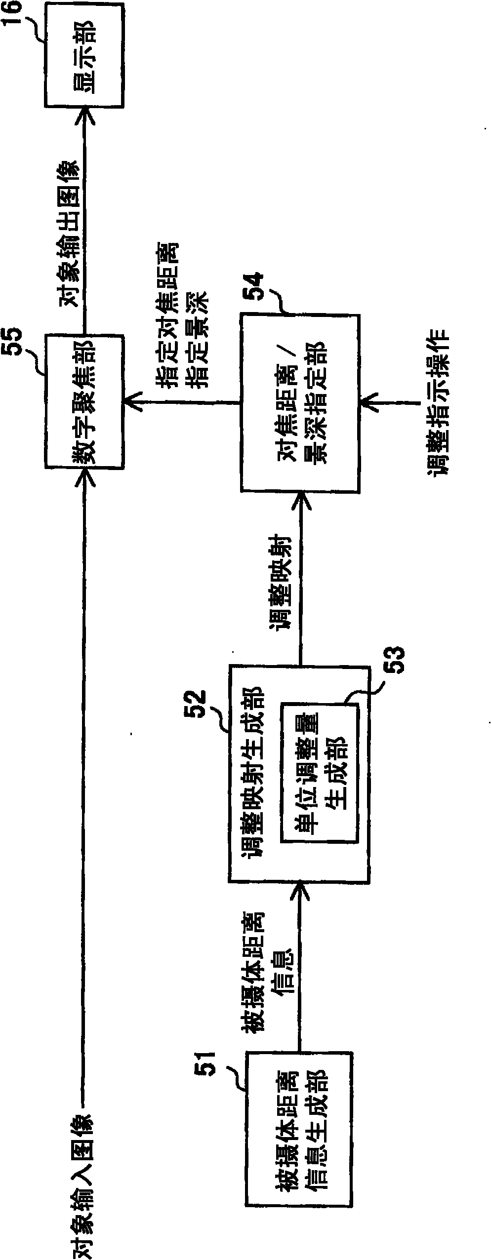
[0105] Utilized in the second embodiment Figure 11 In the configuration shown, the unit adjustment amount is set and the adjustment map is set based on the focus distance of the subject input image 300 detected by the focus state detection unit 56 and the subject distance information from the subject distance information generation unit 51. generate.

[0106] As in the first embodiment, it is considered that the target input image is Figure 5 The case of the image 300 of (a). In this case, the adjustment map generation unit 52 uses the minimum distance d extracted from the subject distance information MIN and the maximum distance d MAX , the focus distance d of the object input image 300 o...

no. 3 Embodiment approach

[0121] A third embodiment of the present invention will be described. In the third embodiment, an example of a digital focusing method performed by the digital focusing unit 55 will be described.

[0122] As a method of changing the focus distance and depth of field of the target input image, the digital focus unit 55 can use any method including known methods. For example, the light field method described above can be utilized. Using the light field method, an output image of an object having an arbitrary focus distance and depth of field can be generated from an input image of an object output by the imaging device 33 . In this case, a known method based on the light field method (eg, the method described in International Publication No. 06 / 039486 or JP-A-2009-224982 ) is used. As mentioned above, in the light field method, the image signal (image data) obtained from the imaging element includes not only the intensity distribution of light on the light receiving surface of...


PUM


Abstract

The invention provides electronic equipment, which can perform simple focusing state adjustment according to intensions of a user. When focusing states (focus distance and depth of field) of an object input image are adjusted through digital focus, object distance information based on the object input image generates a distance distribution (320) indicating the distance distribution of an object. In the distance distribution, frequencies concentrate in a distance range with high presence degree of the object. Step level positions (d[1] to d[6] and d[9] to d[14]) with minute intervals are arranged in the distance range with high presence degree of the object, and step level positions (d[7] and d[8]) with a rough interval are arranged in a distance range with low presence degree of the object. When the user performs a key operation every time for changing the focus distance toward a remote side, the current focus distance is successively changed from a distance at a step level position d[i] to a distance of the step level positions d[i+1], d[i+2], d[i+3], and so on.

Description

technical field [0001] The present invention relates to electronic devices such as digital cameras. Background technique [0002] Conventionally, a function of adjusting the focus state of a target image through image processing has been proposed, and one type of processing that realizes this function is also called digital focus (see, for example, Patent Documents 1 to 3 below). The focus state of the target image is, for example, the depth of field of the target image or the focus distance of the target image (for example, the center of the depth of field). [0003] As a method for determining the in-focus state, there are considered a fully automatic setting method, a subject designation method by the user, and a completely manual setting method. [0004] In the fully automatic setting method, the digital camera automatically performs detection of a main subject and setting of a focus distance and a depth of field suitable for the main subject. [0005] In the subject d...

Claims


Application Information

Patent Timeline
Patent Type & Authority Applications(China)
IPC IPC(8): H04N5/232
CPCH04N23/675H04N23/634
Inventor 津田佳行横畠正大畑中晴雄
Owner SANYO ELECTRIC CO LTD
Why Eureka
Try Eureka