Image pickup apparatus

A technology of camera device and camera department, which is applied in the direction of image communication, TV, color TV parts, etc., and can solve problems such as unresponsiveness

Inactive Publication Date: 2012-02-08
SANYO ELECTRIC CO LTD
View PDF3 Cites 19 Cited by
  • Summary
  • Abstract
  • Description
  • Claims
  • Application Information

AI Technical Summary

Problems solved by technology

In addition, the method of the above-mentioned Patent Document 1 is a technique for warning of the danger of going abroad, and cannot respond to such expectations.

Method used


Image

  • Image pickup apparatus
  • Image pickup apparatus
  • Image pickup apparatus

Examples


no. 1 approach 》

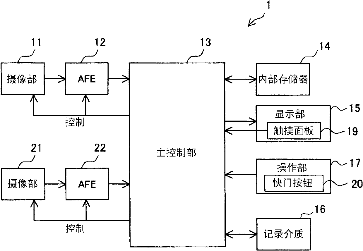
[0036] The first embodiment of the present invention will be described. figure 1 It is an overall schematic block diagram of the imaging device 1 according to the first embodiment. The imaging device 1 is a digital still camera capable of photographing and recording still images or a digital video camera capable of photographing and recording of still images and moving images. The imaging device 1 may be a device that can be mounted on a portable terminal such as a mobile phone.

[0037] The imaging device 1 includes: an imaging unit 11 as a first imaging unit, an AFE (Analog Front End) 12, a main control unit 13, an internal memory 14, a display unit 15, a recording medium 16, an operation unit 17, and an imaging unit as a second imaging unit. Section 21 and AFE22.

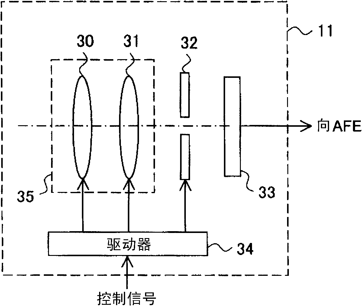
[0038] figure 2 An internal configuration diagram of the imaging unit 11 is shown. The imaging unit 11 has an optical system 35 , an aperture 32 , an imaging element 33 composed of a CCD (Charge Coupled Devi...

no. 2 approach 》

[0087] A second embodiment of the present invention will be described. The second embodiment is an embodiment based on the first embodiment, and the description of the first embodiment can also be applied to the second embodiment for matters not particularly described in the second embodiment.

[0088] The operation of the special shooting mode, which is one of the shooting modes, will be described. In special shooting modes such as Figure 12 As shown, the narrow-angle frame image sequence is displayed as a moving image in the main display area 340, and the wide-angle frame image sequence is displayed as a moving image in the sub-display area 341 (see also Figure 7 (b)). For convenience of description, the phenomenon that the narrow-angle frame image sequence is displayed in the main display area 340 and the wide-angle frame image sequence is displayed in the sub-display area 341 is called narrow-angle main display. A rectangular frame 420 is displayed superimposed on the...


PUM


Abstract

The invention provides an image pickup apparatus. The image pickup apparatus includes a first imaging portion and a second imaging portion that takes an image of the subjects with a wider angle than the first imaging portion. Track of a speficic object is performed on a narrow angle frame image array based on output signals of the first imaging portion and the track of the specific object is also performed on a wide angle frame image array based on output signals of the second imaging portion. The narrow angle frame image array is displayed as a dynamic image in a main display area for displaying frames and wide angle image information is displayed in an auxiliary display area for displaying the frames. The wide angle imaging information indicates a rectangular frame ico corresponding to a pickup range of the first imaging portion, a rectangular frame ico corresponding to a pickup range of the second imaging portion, and an ico of a position of the specific object in the relationships with the pickup ranges of the first imaging portion and the second imaging portion. Therefore, when occurring, frame-out can be prevented easily.

Description

technical field [0001] The present invention relates to imaging devices such as digital cameras. Background technique [0002] In recent years, digital cameras and the like capable of shooting moving images have been popularized for general consumers. When shooting a moving image of a subject of interest using such a digital camera, the photographer checks that the subject of interest is within the shooting range on the monitor of the camera, and then adjusts the zoom ratio, adjusts the shooting direction, etc. . At this time, the subject of interest may be frame-out due to the movement of the subject of interest or the like. That is, the subject of interest moves out of the shooting range. Such exit frequently occurs particularly when the zoom magnification is set to a high magnification. [0003] At the moment of leaving the country, most photographers lose sight of the subject of interest, and most of them cannot recognize how to adjust the shooting direction to accom...

Claims


Application Information

Patent Timeline
Patent Type & Authority Applications(China)
IPC IPC(8): H04N5/232H04N5/76H04N13/239
CPCH04N5/772H04N13/286H04N13/239H04N23/45H04N23/631
Inventor 隈俊毅
Owner SANYO ELECTRIC CO LTD
Why Eureka
Try Eureka