Image processing apparatus

a technology of image processing and apparatus, applied in the field of image processing apparatus, can solve the problems of user difficulty in recognizing the switching of images, user inability to catch up, and difficulty in recognizing the angle of view of images displayed on the display device, etc., and achieve the effect of expanding an area

Active Publication Date: 2009-03-05
DENSO CORP +1
View PDF27 Cites 31 Cited by
  • Summary
  • Abstract
  • Description
  • Claims
  • Application Information

AI Technical Summary

Benefits of technology

[0020]An area having undergone masking processing is, as in accordance with another aspect, gradually diminished from the center of an image that has been outputted by the image output means and displayed on the display device, to the right and left lateral sides thereof. Consequently, when a narrow-angle image is switched to a wide-angle image, a user is likely to have a sense of spread and can recognize that switching has occurred.
[0021]Display subduing to be performed when a wide-angle image is switched to a narrow-angle image, as in accordance with another aspect, is such that before the images are switched, masking processing—the processing of applying a predetermined mask to an image area contained in the wide-angle image alone but not contained in the narrow-angle image—is performed for a predetermined time. Unmasking processing—processing to restore a state attained prior to the masking processing—is then executed simultaneously with the switching of the angles of view.
[0022]According to the display subduing, a user can more readily recognize that a wide-angle image has been switched to a narrow-angle image and can readily recognize to what place in the post-switching image, that is, the narrow-angle image the pre-switching image, that is, the wide-angle image corresponds.
[0023]Moreover, masking processing is, as in accordance with another aspect 1...

Problems solved by technology

However, when such images are switched and displayed, it can be difficult for a user to recognize at what angle of view an image displayed on the display device has been captured.
However, disadvantages exist in the technology described in JP-A-2005-33594 in that, when images are...

Method used


Image

  • Image processing apparatus
  • Image processing apparatus
  • Image processing apparatus

Examples


first embodiment

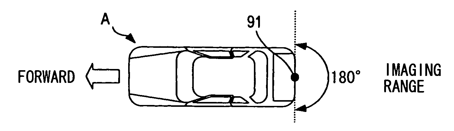
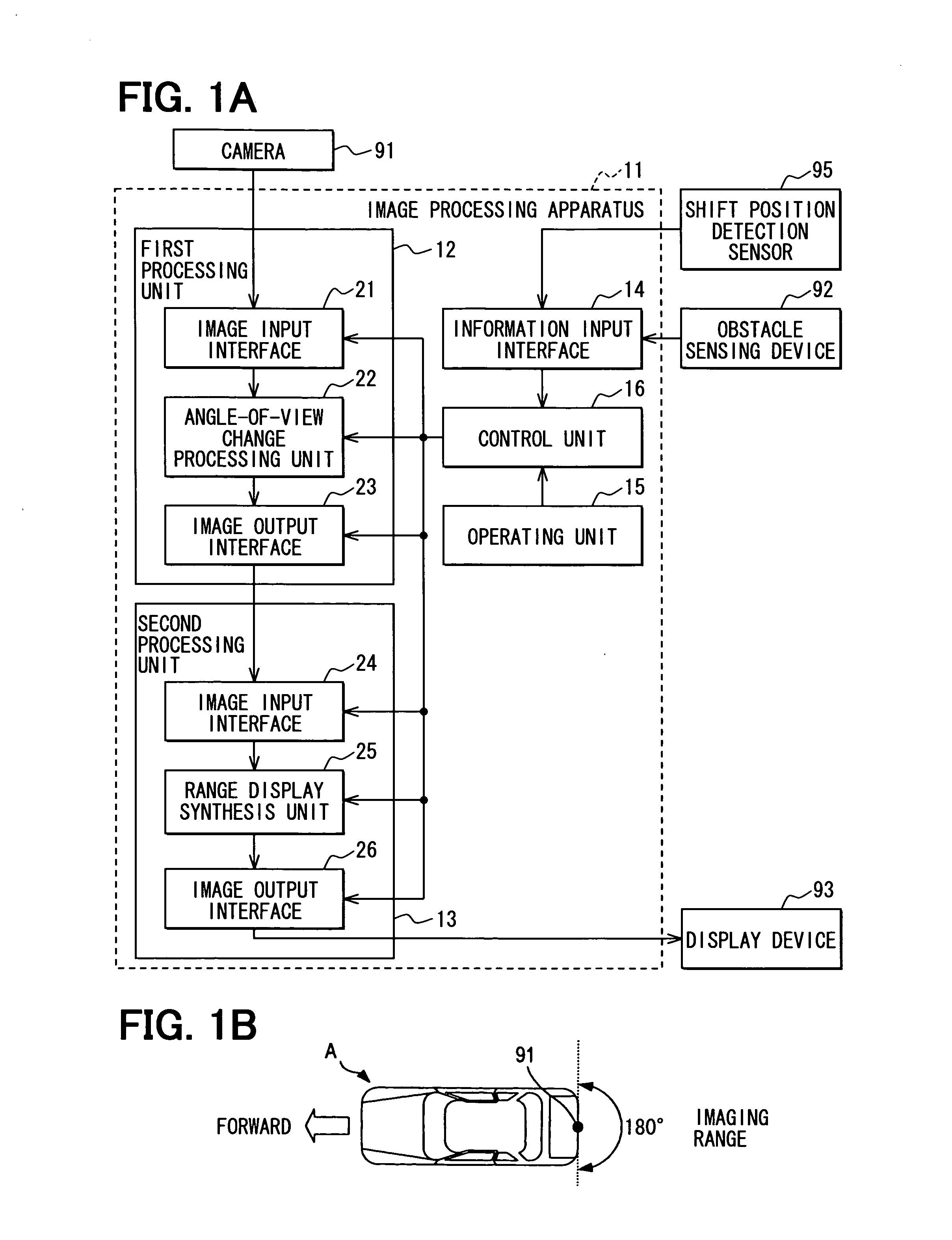
[0042]FIG. 1A is a block diagram for explaining, in connection with a first embodiment, an image processing apparatus 11 and various devices connected thereto such as a camera 91, an obstacle sensing device 92, a display device 93, and a shift position detection sensor 95. The image processing apparatus 11 is a processing apparatus inputting an image of one kind of angle of view or a raw image from the camera 91, switching the raw image and an image of a narrow angle of view produced from the raw image, and displaying the images on the display device 93. The image processing apparatus 11 includes a first image processing section 12, a second image processing section 13, an information input interface 14, an operating unit 15, and a control unit 16.

[0043]The first image processing section 12 can modify the angle of view of an inputted image, can zoom in or out the inputted image, and includes an image input interface 21, an angle-of-view change processing block 22, and an image outpu...

second embodiment

[0067]FIG. 4 is a block diagram explaining an image processing apparatus 41 according to a second embodiment and various devices connected thereto such as a camera 91, an obstacle sensing device 92, and a display device 93. Since the camera 91, obstacle sensing device 92, and display device 93 are identical to those described above in connection with a first embodiment, a description will be omitted.

[0068]The image processing apparatus 41 is a processing apparatus inputting an image of one kind of angle of view, that is, a raw image from the camera 91, switching the raw image and an image of a narrow angle of view produced from the raw image, and displaying the images on the display device 93. The image processing apparatus 41 includes an image input interface 42, an angle-of-view change processing unit 43, an image output interface 44, an information input interface 45, an operating unit 46, and a control unit 47.

[0069]The image input interface 42 is an interface through which a vi...

third embodiment

[0087]Next, the third embodiment will be described with reference to FIG. 7, a block diagram illustrating an image processing apparatus 51 of a third embodiment and various devices connected thereto including, for example, a camera 91, an obstacle sensing device 92, and a display device 93 are connected to the image processing apparatus 51. The camera 91, obstacle sensing device 92, and display device 93 are identical to those of the first embodiment. An iterative description will be omitted.

[0088]The image processing apparatus 51 is a processing apparatus inputting an image of one kind of angle of view or a raw image from the camera 91, switching the raw image and an image of a narrow angle of view produced from the raw image, and outputting the images to the display device 93. The image processing apparatus 51 includes a first image processing section 52, a second image processing section 53, an information input interface 54, an operating unit 55, and a control unit 56.

[0089]The ...


PUM


Abstract

An image processing apparatus permits a user to readily recognize a current state of an angle of view. When an angle of view is switched from a wide-angle to a narrow-angle, range display is performed for a predetermined time prior to the switching. Range display includes a narrow-angle image frame formed with lines indicating a border of an image displayed for a predetermined time prior to the switching. After the predetermined time, a narrow-angle image is displayed and the range display is no longer displayed. The range display allows a user to readily recognize that the wide-angle image has been switched to the narrow-angle image by recognizing to what area in a pre-switching wide angle of view image the post-switching narrow-angle image corresponds.

Description

CROSS-REFERENCE TO RELATED APPLICATIONS[0001]The present application is based on and claims priority to JP 2007-226342 filed Aug. 31, 2007, the entire contents of which are incorporated herein by reference.BACKGROUND OF THE INVENTION[0002]1. Field of the Invention[0003]The present invention is related to processing an image captured by a camera mounted in a vehicle, and more specifically to switching between and outputting multiple images of different angles of view.[0004]2. Description of the Related Art[0005]It is known to use an image processing apparatus to switch images of different angles of view so as to display the images on a display device by employing a camera having a zooming facility or by digitally processing a captured image. However, when such images are switched and displayed, it can be difficult for a user to recognize at what angle of view an image displayed on the display device has been captured.[0006]A technology is proposed for solving the above problem, for e...

Claims


Application Information

Patent Timeline
IPC IPC(8): H04N7/18
CPCB60R1/00B60R2300/301B60R2300/302H04N7/183B60R2300/404B60R2300/70H04N5/232B60R2300/306H04N23/635
Inventor HATTORI, TOSHIHIROIMANISHI, MASAYUKI
Owner DENSO CORP
Why Eureka
Try Eureka