Horizontally polarized wide-angle radar object detection

a wide-angle radar and object detection technology, applied in the field of horizontal polarized wide-angle radar object detection, can solve the problems of limiting system performance, general not well-suited to wide-zone-of-coverage applications, and excluding approaches, so as to improve the wide-angle field of view

Active Publication Date: 2006-03-07
APTIV TECH LTD
View PDF2 Cites 30 Cited by
  • Summary
  • Abstract
  • Description
  • Claims
  • Application Information

AI Technical Summary

Benefits of technology

[0004]The present invention is directed to an improved radar including fixed beam transmitter and receiver antennae that utilize horizontal polarization for improved wide-angle field-of-view through a plastic fascia. In a preferred embodiment, the transmitter antenna transmits ...

Problems solved by technology

Short-range obstacle detection for vehicle back-up and parking aid functions can be achieved with a wide-angle radar system, but cost and packaging considerations force design constraints that tend to limit the system performance.
For example, overall vehicle cost considerations may effectively rule out the use of multiple transce...

Method used


Image

  • Horizontally polarized wide-angle radar object detection
  • Horizontally polarized wide-angle radar object detection
  • Horizontally polarized wide-angle radar object detection

Examples


Embodiment Construction

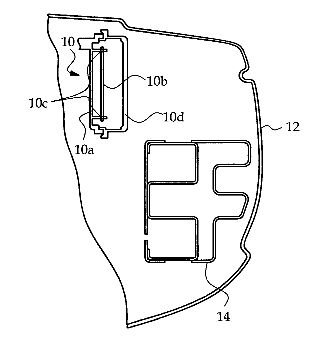
[0011]The radar system of the present invention applies in general to the use of a fixed beam radar in applications requiring a wide-angle zone-of-coverage, where the sensor will be concealed behind a plastic / dielectric panel or fascia. The invention is illustrated herein in the context of a vehicle back-up and parking aid mounted on a vehicle bumper structure, but is applicable to other vehicle systems such as frontal or side object detection systems, and also to non-vehicle systems.

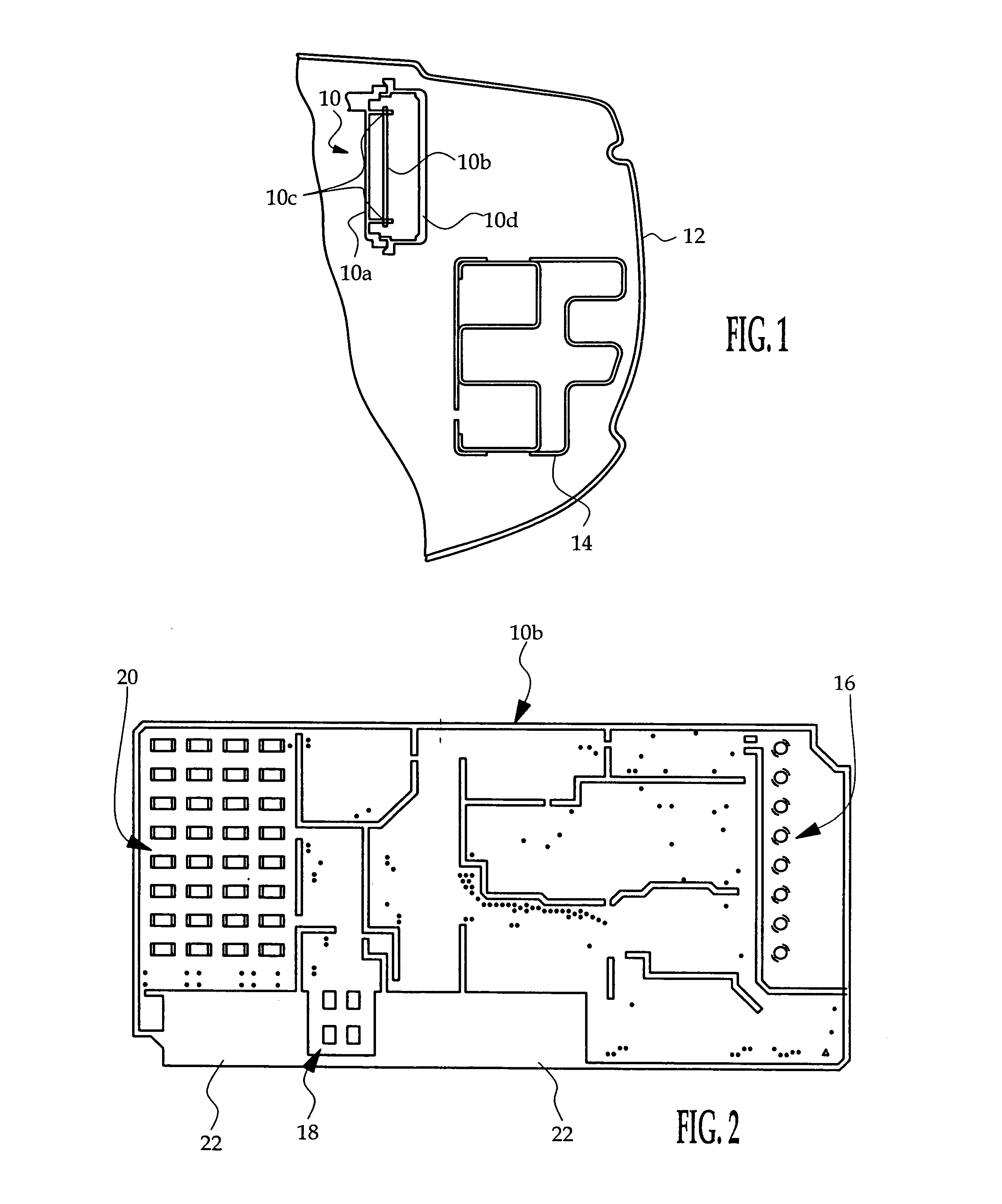
[0012]FIG. 1 depicts a bumper-mounted back-up aid mechanization where a fixed beam radar sensor 10 is concealed behind a plastic fascia 12 surrounding the rear bumper frame 14. The radar sensor includes a base frame 10a mounted to a vehicle frame element (not shown), a multi-layer printed circuit board 10b supported on a set of base frame posts 10c, and a radome or cover 10d mounted on the base frame 10a to enclose and environmentally seal the circuit board 10b.

[0013]Referring to FIG. 2, the circuit bo...


PUM


Abstract

A radar includes fixed beam radar transmitter and receiver antennae that utilize mixed polarization to optimize the object detection field-of-view through an intervening plastic fascia. The transmitter antenna transmits radar energy with slant polarization, a first receiver antenna designed for short-range wide-angle object detection passes only horizontally polarized radar energy, and a second receiver antenna designed for long-range narrow-angle object detection passes only vertically polarized radar energy.

Description

[0001]The present invention is directed to radar object detection, and more particularly to a horizontally polarized radar for achieving a wide-angle field of view through a plastic fascia.TECHNICAL FIELD[0002]Short-range obstacle detection for vehicle back-up and parking aid functions can be achieved with a wide-angle radar system, but cost and packaging considerations force design constraints that tend to limit the system performance. For example, overall vehicle cost considerations may effectively rule out the use of multiple transceivers for meeting wide zone-of-coverage requirements, and radar system packaging and cost considerations may effectively require the use of planar transmit and receive antennas, which in general are not well-suited to wide zone-of-coverage applications. Additionally, vehicle styling and design considerations frequently require the radar system to be concealed behind a plastic fascia panel, such as a bumper fascia, that variably attenuates radar energy...

Claims


Application Information

Patent Timeline
IPC IPC(8): G01S13/93G01S13/931
CPCG01S7/025G01S7/03G01S13/931G01S7/481G01S2013/9314G01S2013/9389G01S2013/93275
Inventor SAPLETAL, GREG J.SHI, SHAWNMCCLURE, KIRK E.
Owner APTIV TECH LTD
Why Eureka
Try Eureka