Laser ablation prototyping of RFID antennas

a technology of rfid antennas and laser ablation, which is applied in the direction of burglar alarm mechanical actuation, removal of conductive materials by irradiation, instruments, etc., can solve the problems of limiting the resolution of the design, preventing theft, counterfeiting, and not allowing “touch-free” tracking

Inactive Publication Date: 2007-06-14
ZIH CORP
View PDF6 Cites 63 Cited by
  • Summary
  • Abstract
  • Description
  • Claims
  • Application Information

AI Technical Summary

Benefits of technology

[0012] In yet other features, the laser ablation RFID prototyping system is configured based on power and speed, pulses, and / or height. The power is greater than an ablation threshold that occurs when chemical bonds of the conductive ink layer begin to breakup. The power is also less than a cutting threshold that occurs when the laser cuts through the substrate.

Problems solved by technology

However, these forms of identification may not protect items from theft, misplacement, or counterfeit, nor do they allow “touch-free” tracking.
However, painting the design on the substrate limits resolution of the design and offers poor control of ink film thickness.
However, cutting designs with a blade limits resolution and offers poor physical stability of design.
However, creating prototypes using proofing techniques is typically time consuming and expensive.

Method used


Image

  • Laser ablation prototyping of RFID antennas
  • Laser ablation prototyping of RFID antennas
  • Laser ablation prototyping of RFID antennas

Examples


Embodiment Construction

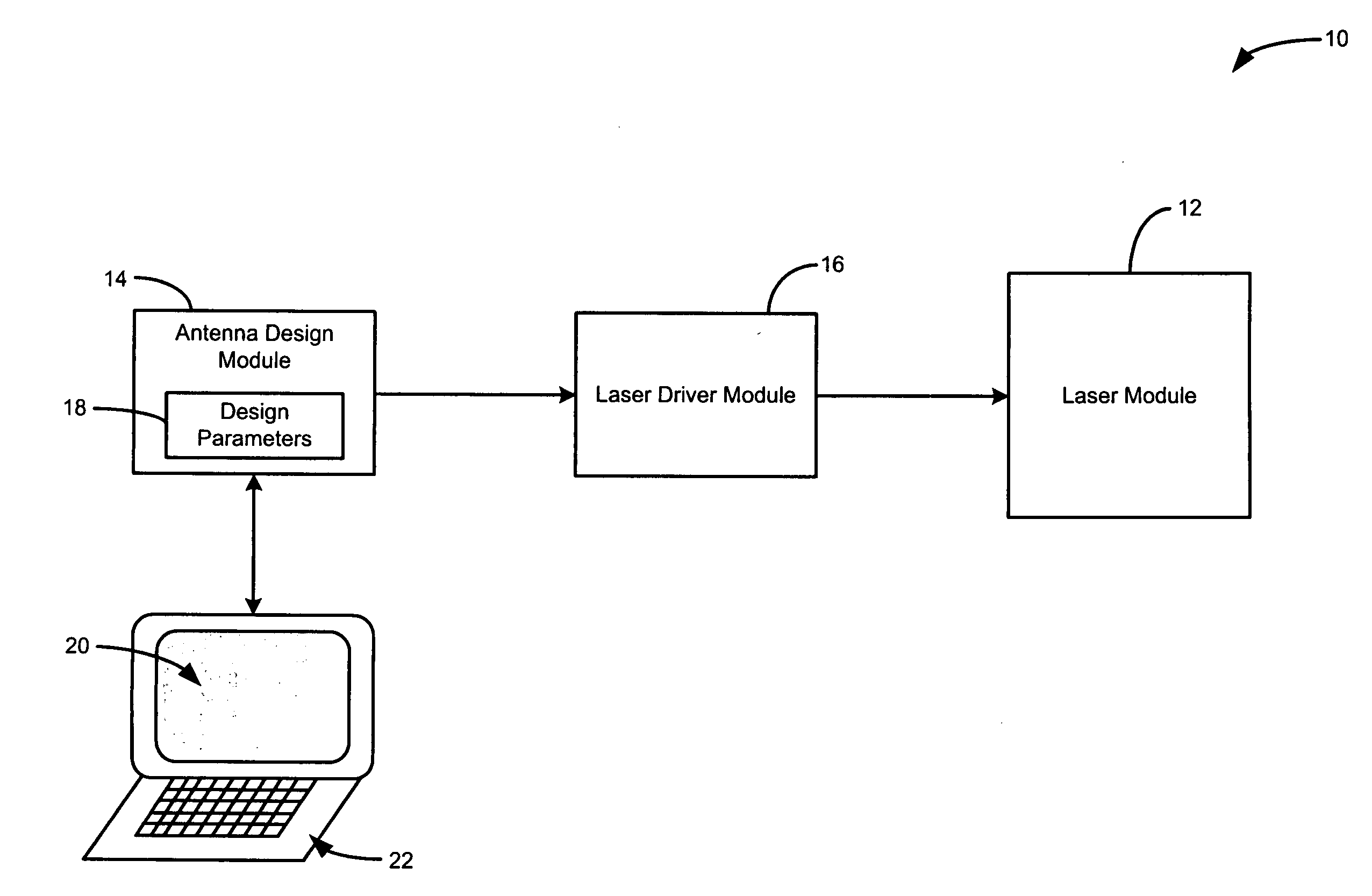
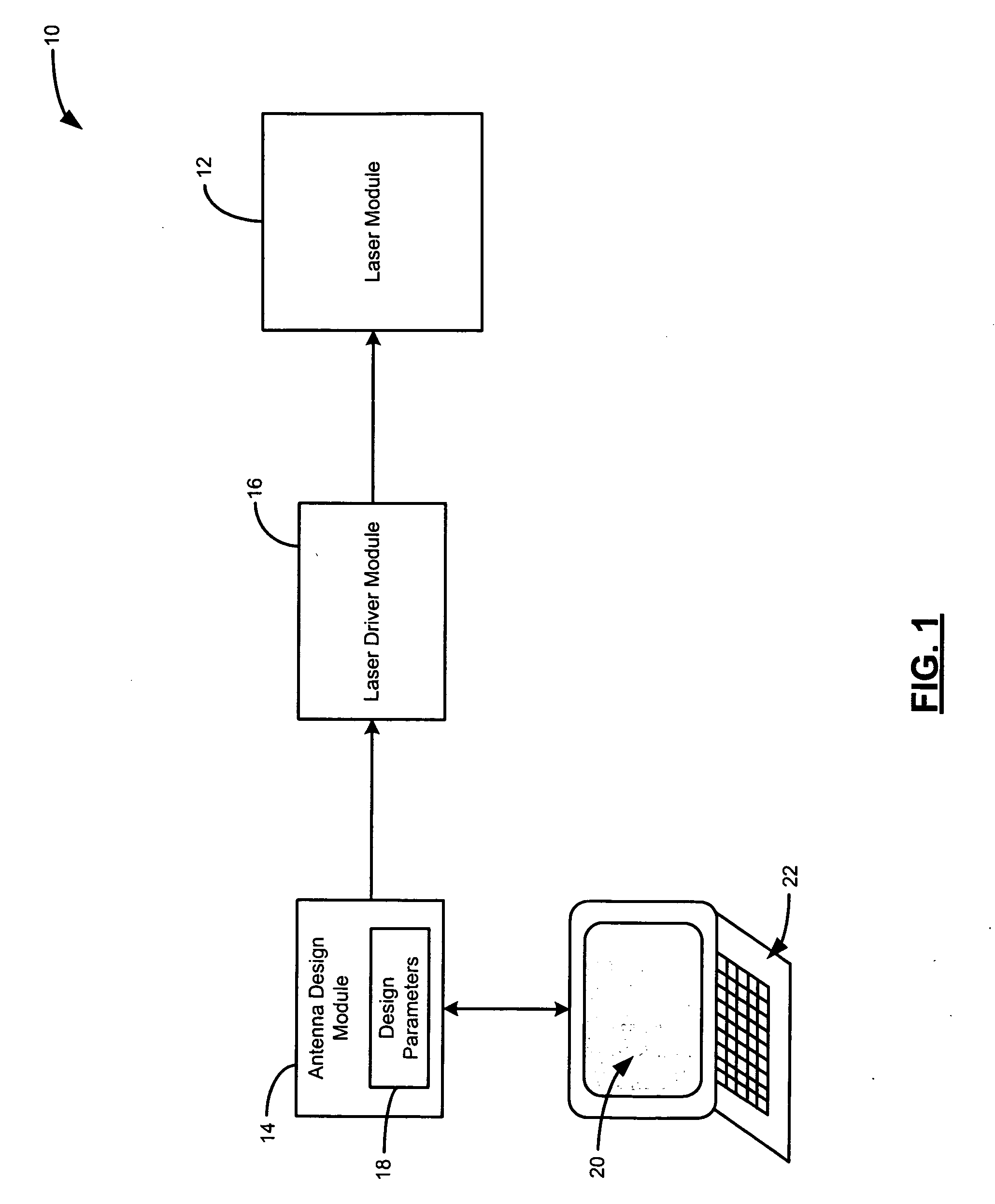
[0022] The following description of the preferred embodiment(s) is merely exemplary in nature and is in no way intended to limit the invention, its application, or uses. For purposes of clarity, the same reference numbers will be used in the drawings to identify similar elements. As used herein, the term module refers to an application specific integrated circuit (ASIC), an electronic circuit, a processor (shared, dedicated, or group) and memory that execute one or more software or firmware programs, a combinational logic circuit, and / or other suitable components that provide the described functionality.

[0023] Laser ablation, in the broadest sense, is removal of material due to incident light. In most metals and glasses / crystals the removal is by vaporization of the material due to heat. In polymers the material can be removed by exposure to laser emissions at a wavelength where the polymer strongly absorbs photons. Ablation occurs when chemical bonds are broken in the polymer. In ...


PUM

PropertyMeasurementUnit
frequenciesaaaaaaaaaa
frequencyaaaaaaaaaa
frequencyaaaaaaaaaa

Abstract

A laser ablation radio frequency identification (RFID) antenna prototyping system includes an antenna design module, an ablation laser, and a laser driver. The antenna design module includes design parameters for an RFID antenna prototype. The laser driver communicates with the antenna design module and the ablation laser. The laser driver uses the design parameters to direct the ablation laser to heat a portion of a conductive ink layer that is formed on a substrate.

Description

FIELD OF THE INVENTION [0001] The present invention relates to radio frequency identification (RFID) antennas, and more particularly to a method of producing prototype RFID antennas. BACKGROUND OF THE INVENTION [0002] Integrated circuits (ICs) are the basic building blocks that are used to create electronic devices. Continuous improvements in IC process and design technologies have led to smaller, more complex, and more reliable electronic devices at a lower cost per function. As performance has increased and size and cost have decreased, the use of ICs has expanded significantly. [0003] One particular type of IC that would benefit from inexpensive mass production involves the use of radio frequency identification (RFID) technology. RFID technology incorporates the use of electromagnetic or electrostatic radio frequency (RF) coupling. Traditional forms of identification such as barcodes, cards, badges, tags, and labels have been widely used to identify items such as access passes, p...

Claims


Application Information

Patent Timeline
Patent Type & Authority Applications(United States)
IPC IPC(8): H01P11/00G08B13/14G06F17/50
CPCG06K19/07749G08B13/2417H05K1/095Y10T29/49016H05K3/046H05K2203/0191H05K2203/081H05K3/027
Inventor FEIN, MICHAEL
Owner ZIH CORP
Why Eureka
Try Eureka