Mobile phone terminal antenna

A mobile phone terminal and antenna technology, applied in the direction of antenna, antenna array, antenna support/installation device, etc., can solve problems such as large space, and achieve the effect of convenient adjustment and convenient antenna design

Inactive Publication Date: 2013-11-13
SHANGHAI AMPHENOL AIRWAVE COMM ELECTRONICS CO LTD
View PDF7 Cites 62 Cited by
  • Summary
  • Abstract
  • Description
  • Claims
  • Application Information

AI Technical Summary

Problems solved by technology

The patent No. US2012206302A1 uses a loop antenna to couple the mobile phone mode to the antenna. In the disclosed technology, antenna radiators are placed above and below the metal shell or on the left and right sides; one of the disclosed embodiments is a metal shell One end is a low-frequency antenna, and the other end is a high-frequency antenna, implementing a double-feed structure. However, if only one feed is used in this solution, the double-feed structure needs a duplexer to realize; at the same time, the antenna structure requires a supporting medium, and the antenna covers the medium. Feed slots, high and low frequencies are independent two antennas occupy a large space, and isolation issues also need to be considered

Method used


Image

  • Mobile phone terminal antenna
  • Mobile phone terminal antenna
  • Mobile phone terminal antenna

Examples


Embodiment 1

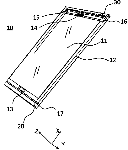
[0063] refer to Figure 1-12 , a mobile phone terminal antenna provided by the present invention is set on a mobile phone terminal 10 to transmit and receive wireless signals. The mobile phone terminal antenna includes a housing and an antenna part, the antenna part is arranged on the upper end and / or the lower end of the housing through an insulating medium, wherein the antenna part is in the shape of a cover with one end open, and the housing and the antenna part are connected to form the entire mobile phone terminal shell.

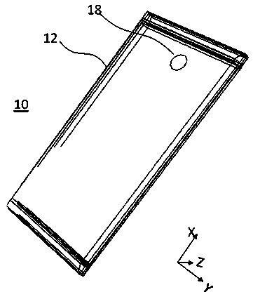
[0064] In this embodiment, the shell is a metal shell 12 with electrical conductivity. Of course, alloys can also be used as the material for the shell, such as stainless steel, magnesium-aluminum alloy, etc., which can be produced by milling, forging, etc., such as Figure 3-Figure 4 shape. The metal shell 12 has a polyhedron shape, including the left and right sides, the bottom surface and the front except for the area where the display screen is se...

Embodiment 2

[0077] refer to Figure 16 , is an alternative embodiment of the present invention, and this embodiment is a modification made on the basis of Embodiment 1. Specifically, in this embodiment, the first circuit part is directly implemented by a grounding branch 28, which is located on the lower end surface of the connection between the metal shell 12 and the main antenna radiation body 22, and the grounding branch 28 is also connected to the metal shell 12 and main antenna 20. In this embodiment, the adjustment of the frequency of the first frequency band in which the main antenna 20 works is realized by the ground branch 28, and the position of the ground branch 28 is closer to the first feeding part 21 than the position of the inductance 27 in Embodiment 1, The frequency of the first frequency band is adjusted by adjusting the distance between the ground branch 28 and the first feeding part 21 . Except for the above improved parts, the rest of this embodiment is the same as ...

Embodiment 3

[0079] refer to Figure 17 and Figure 20 , is an alternative embodiment of the present invention. This embodiment is a modification made on the basis of Embodiment 1, so that the main antenna 20 can realize two low-frequency bands. Specifically, in this embodiment, the first circuit part is realized by using a switch circuit. The first circuit part 60 includes a first switch 61, a first input part 62, a first multi-channel inductance 67, a second multi-channel inductance 68 and a first data control line 64; one end of the first input part 62 is connected to the metal shell 12 and the main antenna radiation body 22, the other end is connected with multi-channel inductors 67 and 68; the first switch 61 has multiple input ports, and the multi-input ports are respectively connected to the first multi-channel inductor 67 and the second multi-channel inductor 68; the first switch 61 may have multiple output terminals, and its output terminals are directly connected to the ground,...


PUM


Abstract

The invention provides a mobile phone terminal antenna. The antenna comprises a metal casing, as well as a main antenna and an auxiliary antenna which are connected with the metal casing through insulating medium, wherein the main antenna is used for receiving and emitting wireless signals; the auxiliary antenna, as a diversity antenna, is used for emitting and receiving signals of GPS / WIFI frequency band; the main antenna is arranged at the lower end of the metal casing and comprises a main antenna radiation body, a first feeding part, an inductor and a second circuit part, the first feeding part and the inductor are positioned at an upper end surface of the connecting part of the main antenna radiation body and the metal casing, and the second circuit part is positioned at a lower end surface of the connecting part of the main antenna radiation body and the metal casing; a switch is arranged in the second circuit part and controls the second circuit part to be grounded or not so as to realize different working frequencies. According to the antenna, the metal casing and the antenna part are integrally formed through injection moulding and other processes. Besides, the switch and the inductor are also arranged, the working states of two frequency bands are realized to meet multi-band communication; the antenna design can be conveniently adjusted.

Description

technical field [0001] The invention relates to the technical field of antenna design, in particular to a mobile phone terminal antenna. [0002] Background technique [0003] Miniaturized multi-band built-in antennas have always been the development direction of handheld communication terminal antennas. The existing antenna forms include multi-frequency monopole antennas, single-loop or double-loop antennas, inverted folded antennas (IFA), and planar inverted folded antennas (PIFA). These antenna types have their own conditions and performance in different handheld communication terminal environments, and different antenna forms can be selected according to different requirements. [0004] Usually mobile terminal equipment includes GSM850 / 900, DCS, PCS, UMTS, and its frequency range is 0.824GHz-0.96GHz, 1.71GHz-2.17GHz. With the continuous development of LTE technology, the frequencies of 1700MHz, 3.5GHz, and 4GHz have attracted much attention. More and more mobile phone...

Claims


Application Information

Patent Timeline
Patent Type & Authority Applications(China)
IPC IPC(8): H01Q5/00H01Q1/36H01Q1/44H01Q1/24H01Q21/00
Inventor 何其娟孙劲
Owner SHANGHAI AMPHENOL AIRWAVE COMM ELECTRONICS CO LTD
Why Eureka
Try Eureka