Film side sealing apparatus with closed-loop temperature control of a heater

a technology of temperature control and sealing apparatus, which is applied in the direction of transportation and packaging, packaging, transit packaging, etc., can solve the problems of difficult cleaning of wires without disturbing the gap setting or flatness of wires, loss of production time, and inability to achieve stable performance of dual side sealers

Inactive Publication Date: 2006-05-25
SHRINK PACKAGING SYST
View PDF12 Cites 23 Cited by
  • Summary
  • Abstract
  • Description
  • Claims
  • Application Information

AI Technical Summary

Benefits of technology

[0011] It is another object of this invention to provide a heat source that closely approximates an ideal sealing temperature of a particular thermoplastic film with a given thickness, and the heat source that cuts the film will operate at precisely the ideal temperature so as to produce consistent film strength seals with no residue and pleasing aesthetics with a wide range of thermoplastic materials, which is not possible with present technology.

Problems solved by technology

Cleaning the wires without disturbing the gap setting or flatness of the wire is very difficult.
All of this results in lost production time.
Further, the performance of the dual side sealer is often not stable over extended periods of operation even when initially adjusted to optimum settings.
A significant cause of this instability is the drift in wire temperatures over time due to drifts in power conditions typical in many factories.
Another inherent problem with the dual wire side sealer is the fact that many side sealer components heat up to undesirably high temperatures during operation of the side sealer as a result of the sealing wires radiating heat and its mounting being in contact with the frame they are mounted on which conducts heat to the main assembly resulting in resin build-up during production runs.
The heat build-up is detrimental to successful side sealing requiring frequent stopping of the machine in order to clean the molten film build-up on the individual wire assemblies.
The resin build-up is a result of unintentional heating of the area of the film that is close to, but outside of, the actual seal area.
This unintentionally heated film becomes soft and is prone to stick to components that it contacts, particularly if the side sealer frame components are already at an elevated temperature.
In addition, the dual wire side sealer has a large parts count, and coupled with the fact that it operates at an overall elevated temperature, the side sealer belts and bearings are subject to frequent failure, resulting in attendant high maintenance costs.
In addition, when the dual wire sealer is inoperable for any reason, it requires sufficient time to cool down in order to restore its operation due to the excessive operating temperature of the entire unit, which frequently reaches temperatures of 135 degrees F. A typical cleaning and resetting will take at least 1 hour, resulting in lost production for that period of time.
However, there is no closed loop control of the temperature of the hot wire and resin build-up occurs requiring frequent maintenance.

Method used


Image

  • Film side sealing apparatus with closed-loop temperature control of a heater
  • Film side sealing apparatus with closed-loop temperature control of a heater
  • Film side sealing apparatus with closed-loop temperature control of a heater

Examples


first alternate embodiment

[0049] Referring to FIG. 8, a front elevational view of the top belt guide 25 is shown having two elongated holes 72a, 72b to facilitate attaching the belt guide 25 to the sides of the side sealer 10 and adjusting the belt guide 25 against the lower portion of V-belt 16, which is positioned between top drive roll 12 and idler roll 14. The ends 71, 77 of the belt guide 25 are curved inwardly at a radius to correspond with the radius of the pulley rolls. In the preferred embodiment shown in FIGS. 8-10, the belt guide 25 is approximately 11 inches long, 2.56 inches high and 0.25 inch thick; however, other sizes of belt guide 25 may be implemented on a side sealer.

[0050] Referring to FIG. 9, a side elevational view of the top belt guide 25 shows a bottom groove 70 having a radius of approximately 0.06 inch so that the belt only protrudes slightly into the groove 70 to minimize any undesired frictional force.

[0051] Referring to FIG. 10, a bottom view of the top belt guide 25 shows the ...

second alternate embodiment

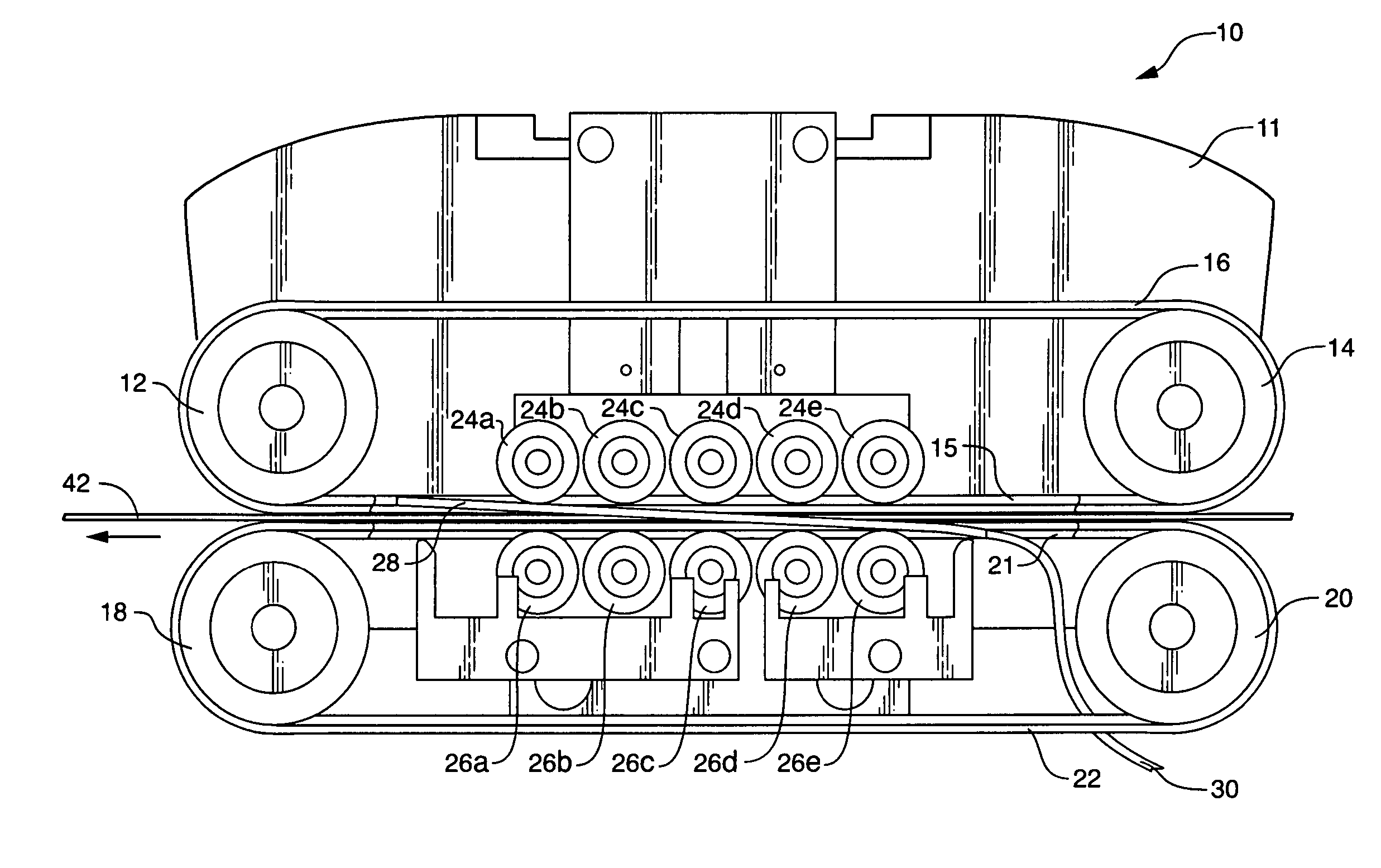
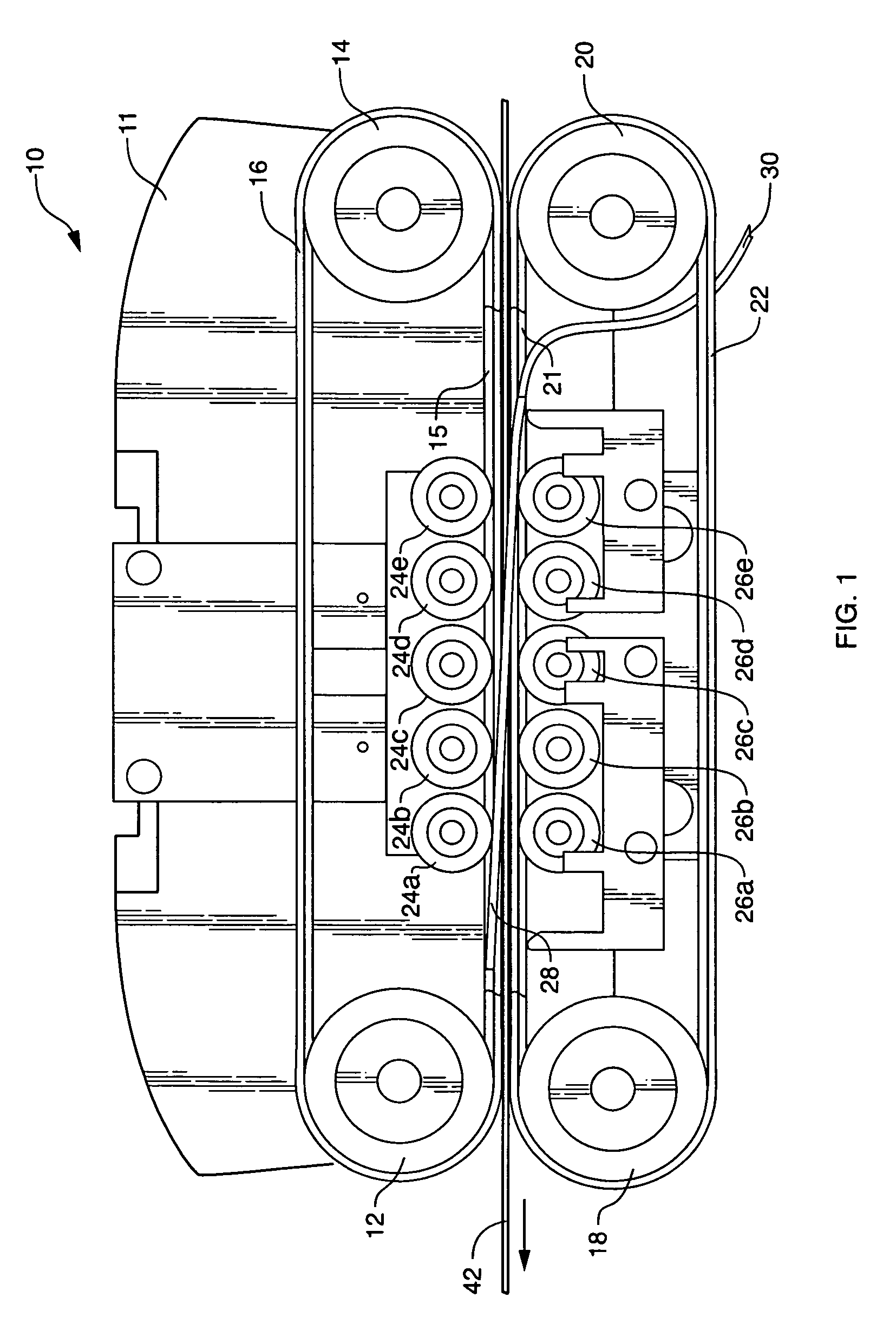
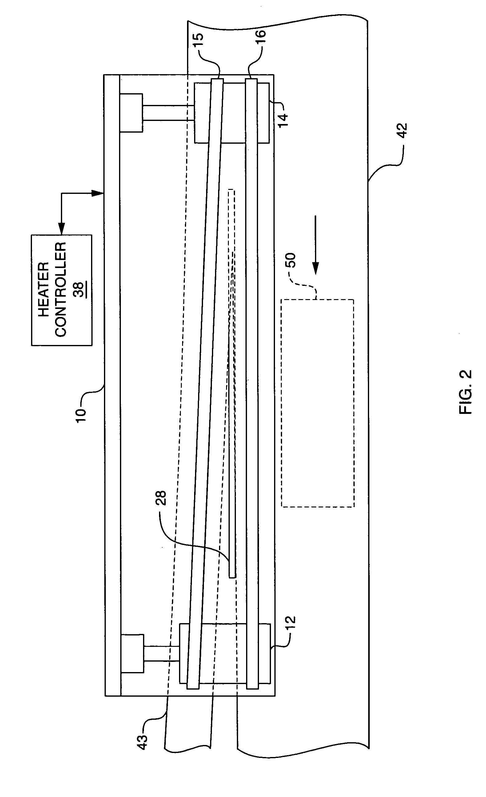
[0056] Referring to FIG. 14, a front elevational view of a second alternate embodiment of a side sealer 100 according to the present invention is shown. Elements of side sealer 100 which are the same as elements of the embodiment shown in FIG. 1 have the same reference number. The side sealer 100 performs a cutting and sealing operation the same as side sealer 10, but because of certain improvements to be described, the side sealer 100 performs a more efficient cutting and sealing operation near edges of a thermoplastic film 42 for covering a package 50 (FIG. 2) by eliminating lateral film 42 slippage while the film 42 is driven through the sealing process by the V-belts 15, 16, 21, 22. In some cases, the amount of thermoplastic film used is reduced with the side sealer 100 embodiment because of increased grip on the film 42. The cutting and sealing is performed using the heater 28. The second alternate embodiment shown in FIG. 14 employs a series of upper rotating rollers 124a-124e...


PUM

PropertyMeasurementUnit
thicknessaaaaaaaaaa
angleaaaaaaaaaa
thickaaaaaaaaaa

Abstract

A side sealing apparatus for a shrink packaging machine comprising closed loop temperature control of a heater for maintaining an optimum temperature for cutting and sealing two layers of thermoplastic film. The heater comprises a cable or cartridge heater with an internal thermocouple, and it is connected to an automatic temperature controller. The heater is mounted on the side sealer apparatus between two sets of top and bottom V-belts mounted around drive rolls and idler rolls. The V-belts provide nip pressure against the film in order to drive the film. In one embodiment, nip pressure is generated by nip rollers on the scrap side of the film, and by low friction belt support guides on the package side of the film. In another embodiment, the belt support guides are replaced with a series of upper and lower nip rollers, and adjustable toggle clamps provide adjustable pressure on the series of upper and lower nip rollers.

Description

[0001] This application is a Continuation-In-Part of prior application Ser. No. 10 / 994,691, filed Nov. 22, 2004, now pending which is herein incorporated by reference.BACKGROUND OF THE INVENTION [0002] 1. Field of the Invention [0003] This invention relates generally to a side sealer of thermoplastic film around a dimensioned article, and in particular to a side sealing apparatus having an internally heated sealing bar integrated with a closed-loop temperature controller operating essentially in free air supported by thin clips in order to minimize heat transfer to the overall assembly, allowing the heater to cut and seal a thermoplastic film in as tight a temperature range as possible, while allowing the overall temperature of the entire unit to operate at close to room temperature. [0004] 2. Description of Related Art [0005] A commonly used side sealer of thermoplastic film in shrink wrapping machines comprises dual hot wires. The hot wires are typically two (2) eight inch heated ...

Claims


Application Information

Patent Timeline
Patent Type & Authority Applications(United States)
IPC IPC(8): B65B7/02
CPCB29C65/7439B29C66/836B29C65/7873B29C66/87441B29C66/90B29C66/91231B29C66/961B65B9/06B65B51/18B65B2051/105B65G15/14B65H37/04B65H2404/25B65H2404/261B65H2404/264B29C66/91212B29C65/305B29C66/91421B29C66/949B29C66/91431B29C66/91641B29C66/91651B29C66/9241B29C65/18B29C66/73921B29C66/8324B29C66/849B29C66/133B29C66/4322B29C65/749B29C66/4312B29C66/8221B29C66/8242
Inventor JAMES, FRANK A.LINDBERG, JEFFREY C.GILBERT, JOHN J.
Owner SHRINK PACKAGING SYST
Why Eureka
Try Eureka