safety textile machine

A textile machine and safety technology, which is applied in the field of safety textile machines, can solve the problems of textile machine operators' injuries and low degree of automation, and achieve the effects of good sealing, improved automation and close contact

Active Publication Date: 2020-04-14
NINGBO WENZE TEXTILE CO LTD
View PDF1 Cites 0 Cited by
  • Summary
  • Abstract
  • Description
  • Claims
  • Application Information

AI Technical Summary

Problems solved by technology

[0004] The above scheme is provided with a slidable dust cover, and the dust cover is fixed on the required position through the locking bolt, which is convenient for the maintenance personnel to overhaul the textile machine, but the above scheme still has the following problems: the textile machine is locked by the locking bolt. After the position of the machine is fixed, there may be a large gap between the dust cover and the workbench. When the dust is sucked through the dust collection pipe, a negative pressure will be generated in the dust cover, and the outside air will flow from the gap. Continuously entering, if the operator passes nearby, the corner of the operator's clothes may be absorbed into the gap, and the textile machine may cause certain injuries to the operator; on the other hand, when the textile machine is overhauled, prevent The dust cover needs to be manually slid by maintenance personnel, and the degree of automation is not high

Method used


Image

  • safety textile machine

Examples


Embodiment Construction

[0018] Further detailed explanation through specific implementation mode below:

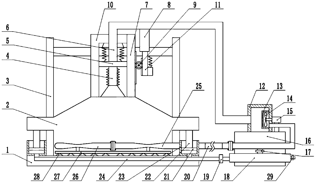
[0019] The reference signs in the drawings of the description include: workbench 1, dust cover 2, guide rod 3, bellows 4, support disc 5, negative pressure tube 6, second rack 7, bypass tube 8, gear 9, Pressure rod 10, first rack 11, negative pressure box 12, filter cover 13, negative pressure vane 14, motor 15, dust box 16, one-way valve 17, air bag 18, program-controlled valve 19, hose 20, piston 21 , Push rod 22, piston cylinder 23, intake pipe 24, first venturi pipe 25, second venturi pipe 26, adsorption pipe 27, suction cup 28, pressure relief valve 29.

[0020] The embodiment is basically as attached figure 1 Shown: safety textile machine, including workbench 1, guide rod 3 and dust cover 2, guide rod 3 is welded on workbench 1, dust cover 2 is vertically slidably connected to guide rod 3, dust cover 2 The bottom of the workbench 1 is covered with a rubber pad, the top of the dust cover 2...


PUM


Abstract

The invention discloses a safety type textile machine. The safety type textile machine comprises a workbench, a guide bar and a dust cover. The bottom of the dust cover is coated with a rubber blanket. A bellows communicates with the top of the dust cover. A negative pressure box is fixed to the workbench. A negative pressure pipe communicates between the negative pressure box and the bellows. A negative pressure blade is rotatably connected with the inside of the negative pressure box. A venturi tube is fixed to the dust cover. An adsorption tube communicates with the throat of the venturi tube. The adsorption tube communicates with a sucker. The negative pressure box communicates with a wind outlet pipe. A filter screen is installed at the inlet of the wind outlet pipe. The outlet of theventuri tube communicates with the dust cover. The wind outlet pipe communicates with a branch pipe. The branch pipe communicates with an air bag. A piston cylinder is fixed to the workbench. A pushrod is fixed to a piston. The push rod abuts against the dust cover. An air inlet pipe communicates with the air bag. Compared with the prior art, the rubber blanket and the sucker are arranged, so that the safety of the textile machine is improved; and the dust cover is enabled to slide by air, so that the difficulty of sliding of the dust cover is reduced, and the degree of automation is improved.

Description

technical field [0001] The invention belongs to the field of textile equipment, in particular to a safety textile machine. Background technique [0002] In recent years, in order to improve the quality of the working environment in textile machine workshops, most textile enterprises have begun to adopt dust-free textile machines. The dust-free textile machines are designed as closed structures, and dust suction pipes are used to suck out the dust on the workbench, so as to realize the efficiency of dust removal. Purpose; however, when the dust-free textile machine breaks down and needs to be repaired, the closed structure design requires the maintenance personnel to disassemble the closed structure and carry out maintenance, which makes the maintenance personnel very troublesome and reduces the maintenance efficiency. During the process, some heavy parts are easy to fall and hurt the instep of the operator, which poses a certain safety hazard. [0003] In order to solve the...

Claims


Application Information

Patent Timeline
Patent Type & Authority Patents(China)
IPC IPC(8): B08B15/04B08B5/04B08B13/00B01D46/10
CPCB01D46/10B08B5/04B08B13/00B08B15/04
Inventor 许根海
Owner NINGBO WENZE TEXTILE CO LTD
Why Eureka
Try Eureka