Macro/micro driven large travel high-speed nano-precision plane positioning system

A plane positioning, large stroke technology, applied in the direction of measuring devices, instruments, optical devices, etc., can solve the problems of insufficient stroke, speed/acceleration and accuracy

Active Publication Date: 2006-02-08
CHANGZHOU MINGSEAL ROBOT TECH CO LTD
View PDF0 Cites 40 Cited by
  • Summary
  • Abstract
  • Description
  • Claims
  • Application Information

AI Technical Summary

Problems solved by technology

[0003] The purpose of the present invention is to overcome the problem that the existing high-speed and high-precision positioning system has insufficient stroke, speed/ac

Method used


Image

  • Macro/micro driven large travel high-speed nano-precision plane positioning system
  • Macro/micro driven large travel high-speed nano-precision plane positioning system
  • Macro/micro driven large travel high-speed nano-precision plane positioning system

Examples


specific Embodiment approach 1

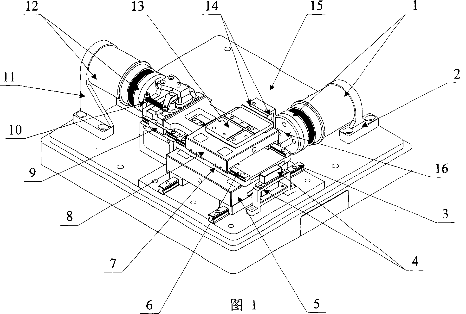
[0005] Specific embodiment one: (see Figure 1- Figure 6 ) This embodiment consists of X-axis linear voice coil motor (mover / stator) 1, X-axis motor base 2, X-axis guide rail 3, X-axis dual linear grating 4, X-axis macro / micro motion platform 5, Y-axis guide rail 6. Y-bearing bearing stage 7, Y-axis macro / micro-motion stage 8, XY-axis decoupling guide rail 9, XY-axis decoupling mechanism 10, Y-axis motor base 11, Y-axis linear voice coil motor (mover / stator) 12. The working platform 13, the Y-axis double linear grating 14 and the base 15, the stator of the X-axis linear voice coil motor 1 is fixed on the X-axis motor base 2, and the X-axis motor base 2 is fixed on the base 15. The stator of the Y-axis linear voice coil motor 12 is fixed on the Y-axis motor base 11, the Y-axis motor base 11 is fixed on the base 15, the mover of the X-axis linear voice coil motor 1 and the X-axis macro / micro motion platform 5Fixed connection, the mover of the Y-axis linear voice coil motor 12 is fix...

specific Embodiment approach 2

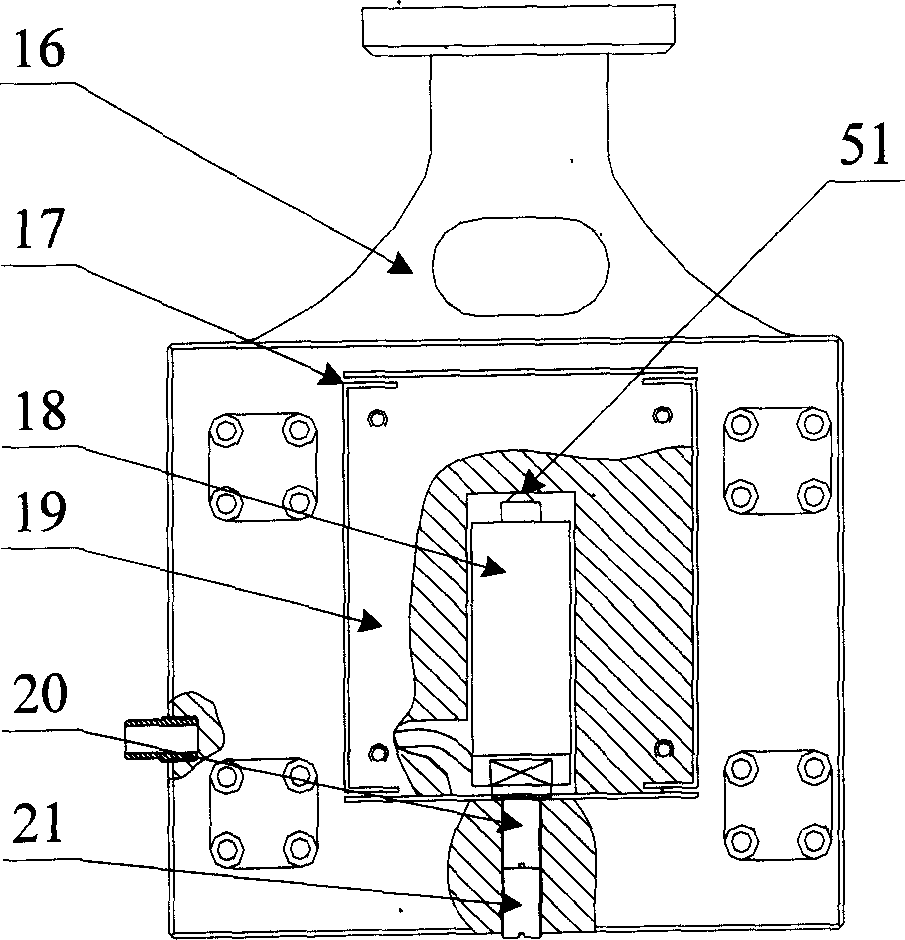
[0006] Specific implementation manner two: (see figure 2 ) In this embodiment, the end of the X-axis piezoelectric ceramic 18 connected to the X-axis micro-motion platform 19 is a spherical shape 51. The other composition and connection relationship are the same as in the first embodiment.

specific Embodiment approach 3

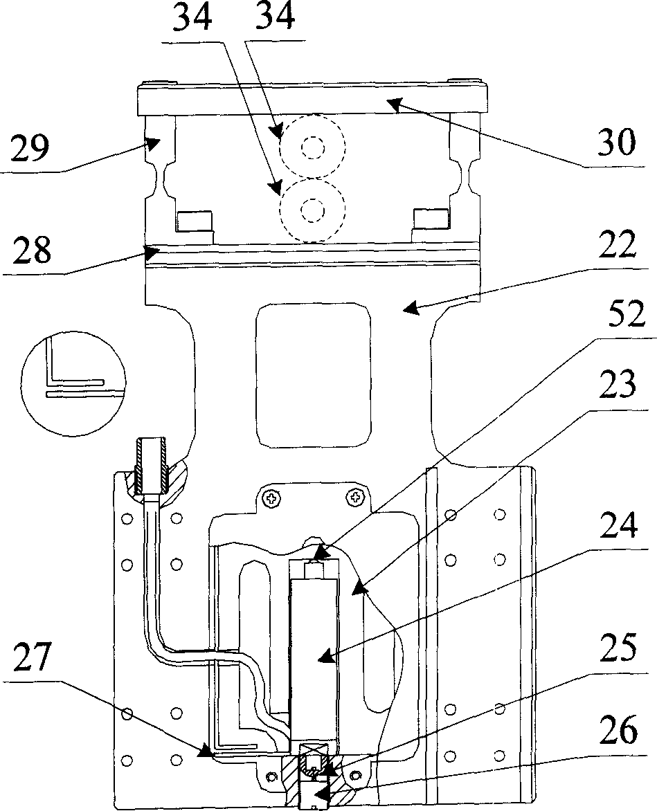
[0007] Specific implementation manner three: (see image 3 ) In this embodiment, the end of the Y-axis piezoelectric ceramic 24 connected to the Y-axis micro-motion platform 23 is a spherical 52. The other composition and connection relationship are the same as in the first embodiment.


PUM


Abstract

The invention relates to a plane orientating system with large stroke, high speed nanometer stage precision and macro/micro dual driven. The X-shaft flexible hinge is fixed between the X-shaft micro moving platform 19 and X-shaft macro moving platform 16; the X-shaft piezo-electric ceramic 18 is posited inside the X-shaft micro moving platform 19; the cushioning hinge 29 is fixed between the inner guide 28 and the outer guide 30; one end of Y-shaft piezo-electric ceramic 24 is connected with Y-shaft micro moving platform 23; two bearings 34 are separately rotating connected with inner guide 18 and outer guide 30 of the Y-shaft macro/micro moving platform 8. The working rage is 25mmX25mm; the resolution is 10nm; the repetition orientating precision is 20nm; the maxim speeds of X-shaft and Y-shaft are separately at 50m/s2 and 100m/s2.

Description

Technical field: [0001] The invention relates to a plane positioning system. Background technique: [0002] Integrated circuit (IC) packaging, micro-electromechanical system (MEMS) manufacturing and other fields have an increasingly urgent need for large travel (cm level), high speed (m / s level) and high precision (μm to nm level) positioning systems. However, the current problems are: 1. The traditional planar positioning system of the XY table with a series structure, because the upper platform is used as the work load of the base platform, greatly increases the inertia of the base platform and limits the speed and acceleration of the entire system. The efficiency of the system is low. 2. The existing parallel structure XY workbench type planar positioning system only uses a single drive device such as a rotating motor + ball screw, linear motor or voice coil motor. Although it can achieve a large range of motion, its accuracy is only Can meet micron or sub-micron requirements....

Claims


Application Information

Patent Timeline
IPC IPC(8): G01B21/02G01B11/02G01B5/02
Inventor 孙立宁刘延杰节德刚荣伟彬曲东升
Owner CHANGZHOU MINGSEAL ROBOT TECH CO LTD
Why Eureka
Try Eureka