Sole structure for a cleated shoe

a technology of cleated shoes and outsoles, which is applied in the field of cleated shoes, can solve the problems of decreased traction of shoes, slippage between, and the plantar surface of the forefoot portion of the foot cannot be closely contacted with the outsole, so as to improve the traction of shoes and enhance fittability

Inactive Publication Date: 2005-08-30
MIZUNO CORPORATION
View PDF8 Cites 43 Cited by
  • Summary
  • Abstract
  • Description
  • Claims
  • Application Information

AI Technical Summary

Benefits of technology

[0009]According to the present invention, because the first and second bulge each has a sectional shape conforming to a shape of a forefoot portion of a foot that has been flexed, when the forefoot portion has been flexed during running the flexed forefoot portion can be closely contacted to a concave region of the first and second bulge, thereby enhancing fittability. As a result, a gripping force can be securely transmitted from a plantar surface of a foot to the ground at the time of flexing a forefoot portion, thereby improving traction performance of a shoe.
[0012]A third bulge that protrudes downwardly toward the ground surface may be provided on the outsole at a position corresponding to a first distal phalanx of a foot of a shoe wearer. In this case, when kicking the ground the first toe can be closely contacted with a concavity of the third bulge, thereby enhancing fittability. As a result, a gripping force can be securely transmitted from the first toe to the ground surface when kicking the ground, thereby improving traction performance of a shoe.
[0014]A fourth bulge that protrudes downwardly toward the ground surface may be provided on the outsole at a region corresponding to each phalangeal joint between each distal phalanx and each middle phalanx of a second to fifth toe of a foot of a shoe wearer. In this case, when kicking the ground the second to fifth toe can be closely contacted with a concavity of the fourth bulge, thereby enhancing fittability. As a result, a gripping force can be securely transmitted from the second to fifth toe to the ground surface when kicking the ground, thereby improving traction performance of a shoe.
[0018]A midsole formed of a soft elastic material may be disposed at least at a forefoot portion of the upper surface of the outsole. In this case, when stepping onto the forefoot portion of the outsole, the midsole elastically deforms in accordance with the shape of a plantar surface of a foot. Thereby, an upper surface of the midsole can be made in a shape conforming to a shape of a forefoot portion of a foot irrespective of different shapes of each individual. As a result, at the time of stepping movement of a forefoot portion of a foot onto the outsole forefoot region, the forefoot portion of a foot can be closely contacted with the outsole via a midsole irrespective of different shapes of plantar surfaces, thereby further enhancing fittability. A gripping force can thus be securely transmitted from a foot to the ground surface and traction of a shoe improves. In this case, thrust from the cleats can be relieved by the midsole.

Problems solved by technology

Therefore, in a prior art shoe, even when fastening a tightening means, a plantar surface of a forefoot portion of a foot cannot be closely contacted with the outsole.
Unless such a part of the plantar surface is closely contacted with the outsole, a slippage may occur between the plantar surface of a foot and the outsole of a shoe during running.
Thereby, a gripping force of a foot relative to the ground through the outsole cannot be securely transmitted to the ground, which results in decrease in traction of a shoe.
Therefore, in a prior-art cleated track shoe, an effective countermeasure is needed that can not only improve traction performance but also efficiently tolerate thrust from the cleats.

Method used


Image

  • Sole structure for a cleated shoe
  • Sole structure for a cleated shoe
  • Sole structure for a cleated shoe

Examples


Embodiment Construction

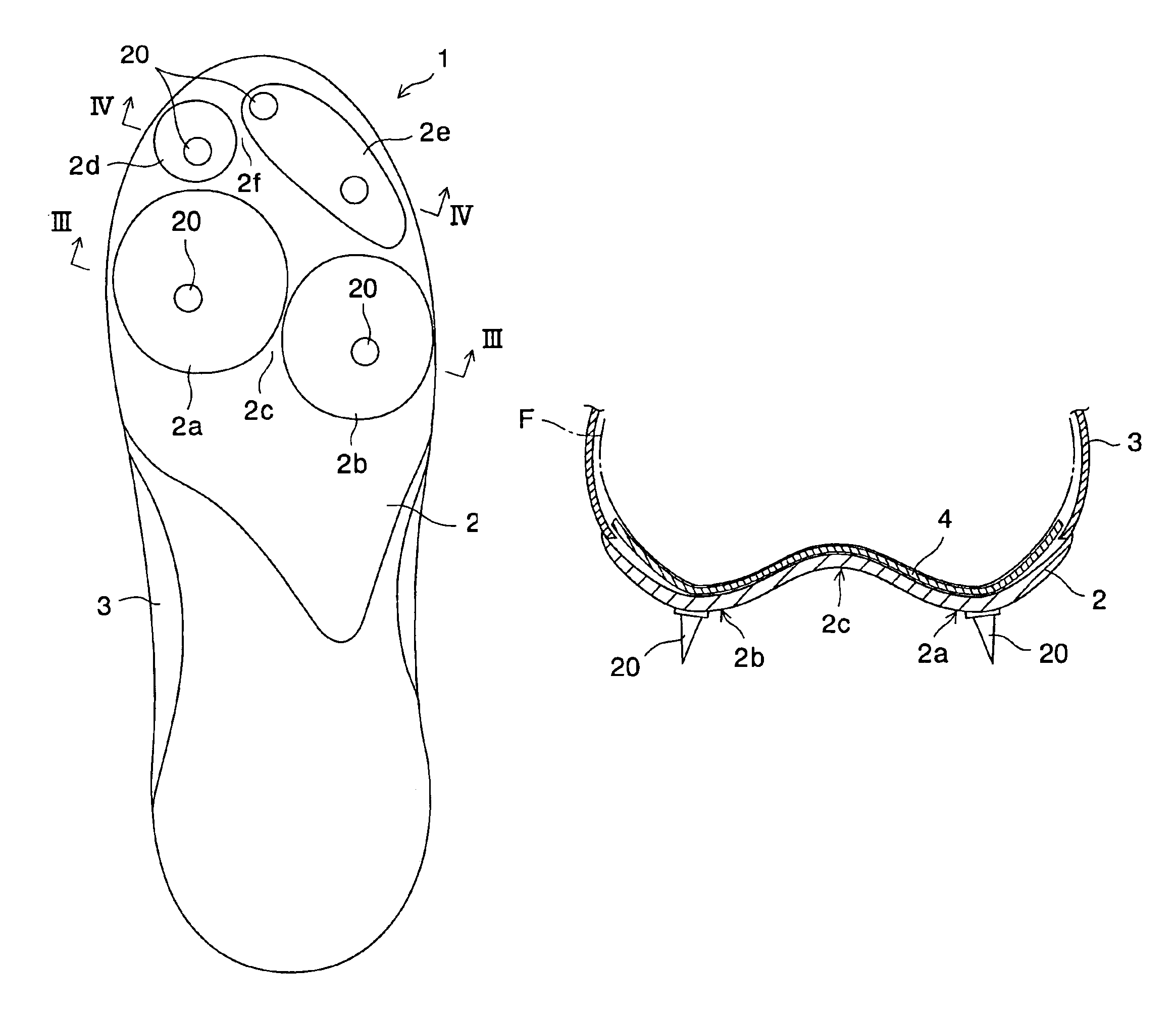
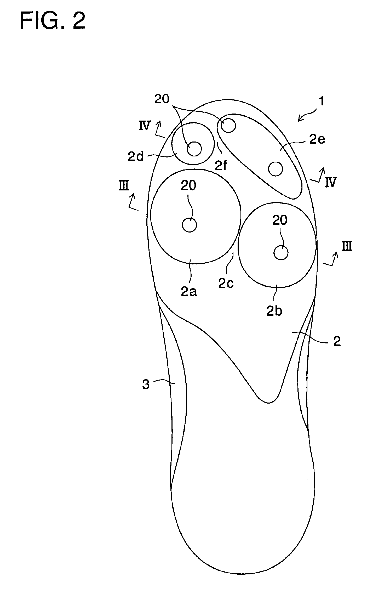
[0030]Referring now to the drawings, FIG. 2 shows a cleated track shoe 1 having an outsole 2 and an upper 3 attached on the outsole 2.

[0031]The outsole 2 is, as shown in FIG. 3, a thin plate member and may be formed of a hard synthetic resin. A plurality of cleats 20 are fitted on the bottom surface of the outsole 2. These cleats 20 may be formed of ceramic, metal, hard synthetic resin, or the like.

[0032]The forefoot portion of the outsole 2 is formed with a first bulge 2a and a second bulge 2b. Both of the bulges 2a, 2b protrude downwardly toward the ground surface, as shown in FIG. 3. Between the first and second bulges 2a, 2b may be formed a concavely curved portion 2c to smoothly connect these bulges 2a and 2b. Some of the cleats 20 are located on the convexly curved surfaces of the first and second bulges 2a, 2b. More preferably, one of the cleats 20 is located on a top centered position, i.e. the most protruded position, of a corresponding bulge 2a, 2b.

[0033]The forefoot port...


PUM


Abstract

A track spiked shoe or a running shoe has a thin-plate-like outsole formed of a hard synthetic resin and having a plurality of cleats or studs on a ground contact surface thereof. The outsole has a first and second bulge each protruding downwardly toward the ground surface. The first bulge is located at a position that corresponds to a thenar eminence of a foot of a shoe wearer and the second bulge at a position that corresponds to a hypothenar eminence of a foot of a shoe wearer. The first and second bulge each has a configuration that conforms to a shape of a forefoot portion of a foot that has been flexed. Some of the cleats are provided on a convexly curved surface of the first and second bulge.

Description

BACKGROUND OF THE INVENTION[0001]The present invention relates generally to a cleated shoe or a shoe having cleats in use for track and field, soccer, rugby, baseball, golf, or the like. More specifically, the present invention pertains to an improvement in a sole structure of a cleated shoe for the purpose of advanced traction performance due to an improved fittability between a sole and a plantar surface of a foot and also for the purpose of dispersion of thrust from the cleats.[0002]In cleated shoes for track and field, various kinds of tightening means such as belts, shoelaces, or the like have been used in order to tightly fasten a shoe to a foot of a shoe wearer. In such shoes, a tightening means such as belts or shoelaces presses a foot of a shoe wearer via an upper of a shoe against an outsole.[0003]An outsole of such cleated shoes is generally formed to conform to the shape of a foot in the longitudinal direction, but not in the transverse direction. However, especially, a ...

Claims


Application Information

Patent Timeline
Patent Type & Authority Patents(United States)
IPC IPC(8): A43C15/00A43C15/16A43B13/26A43B13/14A43B5/00A43B5/02A43B5/06
CPCA43B5/001A43B5/02A43B5/06A43B7/141A43B13/14A43B13/26A43C15/16
Inventor OOREI, TAKESHI
Owner MIZUNO CORPORATION
Why Eureka
Try Eureka