Impression post and temporary abutment and method of making dental restoration

a dental restoration and impression post technology, applied in the field of dental implantogy, can solve the problems of dental surgeons finding that an unusually high torque is required in order to implant the device, implant damage, various forms of damage, etc., and achieves the effect of facilitating the torque limitation, facilitating the construction of a properly fitting device, and being easy to shape or modify

Inactive Publication Date: 2006-11-21
ZIMMER DENTAL INC
View PDF109 Cites 24 Cited by
  • Summary
  • Abstract
  • Description
  • Claims
  • Application Information

AI Technical Summary

Benefits of technology

[0021]To provide certain of the advantages of the invention, it is preferred that the material from which the fixture mount is fabricated be a plastic, such as a thermoset plastic or a thermoplastic. These materials, in addition to facilitating the torque limitation desired of the present invention, also yield a fixture mount that may readily serve as an abutment for a temporary prosthesis, one that is easy to shape or modify by a dental surgeon during the same procedure in which the implant is installed. The fixture mount and abutment thus contemplated by this embodiment of the invention may include longitudinal channels and circumferential grooves on the outer surface to prevent rotation of the temporary prosthesis. Further the channels and grooves ensure retention of the fixture mount / abutment in the impression materials that are typically used to transfer the position and orientation of the implant in the mouth to a dental stone model. In this manner, the fixture mount is therefore also particularly suited for use as an impression post employed to facilitate the construction of a properly fitting and aesthetically pleasing permanent prosthesis.
[0022]More specifically, the state of the art in implant dentistry is to place the implant, take an impression immediately after placement, and then to provide the patient with a temporary abutment and temporary prosthesis all in the same session. This procedure minimizes the time required to complete the implant restoration because fabrication of the final or permanent prosthesis can begin based on the impression taken at the time of surgery, and because both hard and soft tissue healing can begin with the temporary abutment in place. Further, the patient leaves the surgery with an aesthetically pleasing, and in many cases, functional restoration and may not be required to return to the dental office until the final prosthesis has been fabricated. The plastic fixture mount of certain preferred embodiments is thus particularly suited to perform multiple functions: to limit torque applied to the implant during installation; to provide an impression post that supplies implant location and orientation to the dental laboratory; and to provide an abutment to support a temporary prosthesis.

Problems solved by technology

For example, where the bone density is greater than anticipated, the dental surgeon may find that an unusually high torque is required in order to implant the device.
Presently, if the surgeon believes, based on tactile feedback, that the implant is experiencing excessive resistive force, such that a potentially damaging torque would have to be applied in order to install the implant, the surgeon must extract the then partially-installed implant.
If this procedure is not followed and, instead, an excessive torque is applied to the implant, the implant may become damaged.
Such damage may take various forms.
For example, the coating that is applied to the surface of the implant and that is important for enhancing bone growth may be scrapped off the implant or otherwise damaged.
Furthermore, with increasing torque, the end of the implant that receives the applied torque may become damaged, much the way the head of a screw or bolt becomes stripped or rounded off.
Finally, it is possible that the implant would fracture with excessive torque applied.
In each instance, such damage typically would necessitate removal of the damaged implant, thereby lengthening the time required for the surgical procedure and, potentially, increasing the discomfort to the patient.
Further, with excessive torque applied to the top or driven end of the implant via the drive tool and fixture mount, the damage to the end of the implant may be such that it becomes impossible to simply back the implant out of the osteotomy using the drive tool and the fixture mount.
This can further complicate the surgical procedure.
In such instances, the fixture mount itself is discarded and the patient may be deprived of the opportunity of having a temporary prosthesis fitted at the end of the initial surgical procedure and must instead suffer the inconvenience of returning for a second procedure at a time when the temporary abutment and prosthesis can be installed.
Although it would be desirable for the dental surgeon himself to modify the fixture mount “chair-side,” rather than sending the piece offsite to be altered or reconfigured for use as a temporary abutment, for example, the tools available to the dental surgeon typically limit his ability to shape the fixture mount.
That factor, coupled with the very small size of the fixture mount, makes it extremely difficult for the dental surgeon to make precise chair-side modifications to the fixture mount.

Method used


Image

  • Impression post and temporary abutment and method of making dental restoration
  • Impression post and temporary abutment and method of making dental restoration
  • Impression post and temporary abutment and method of making dental restoration

Examples


Embodiment Construction

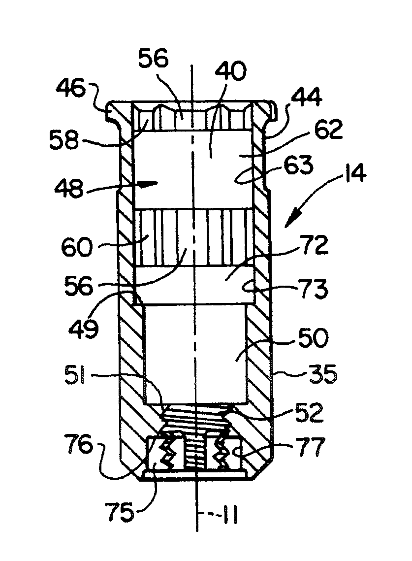
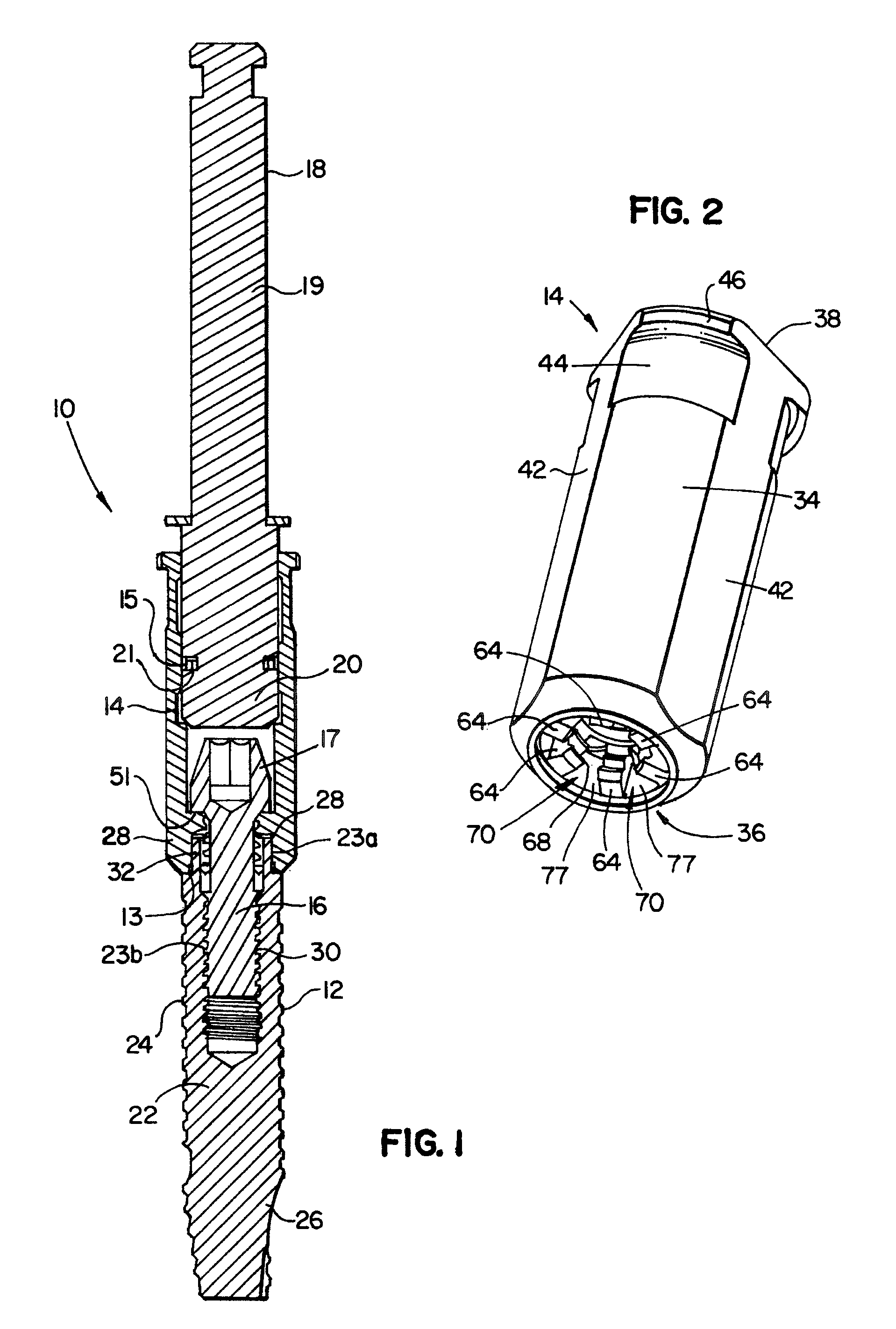
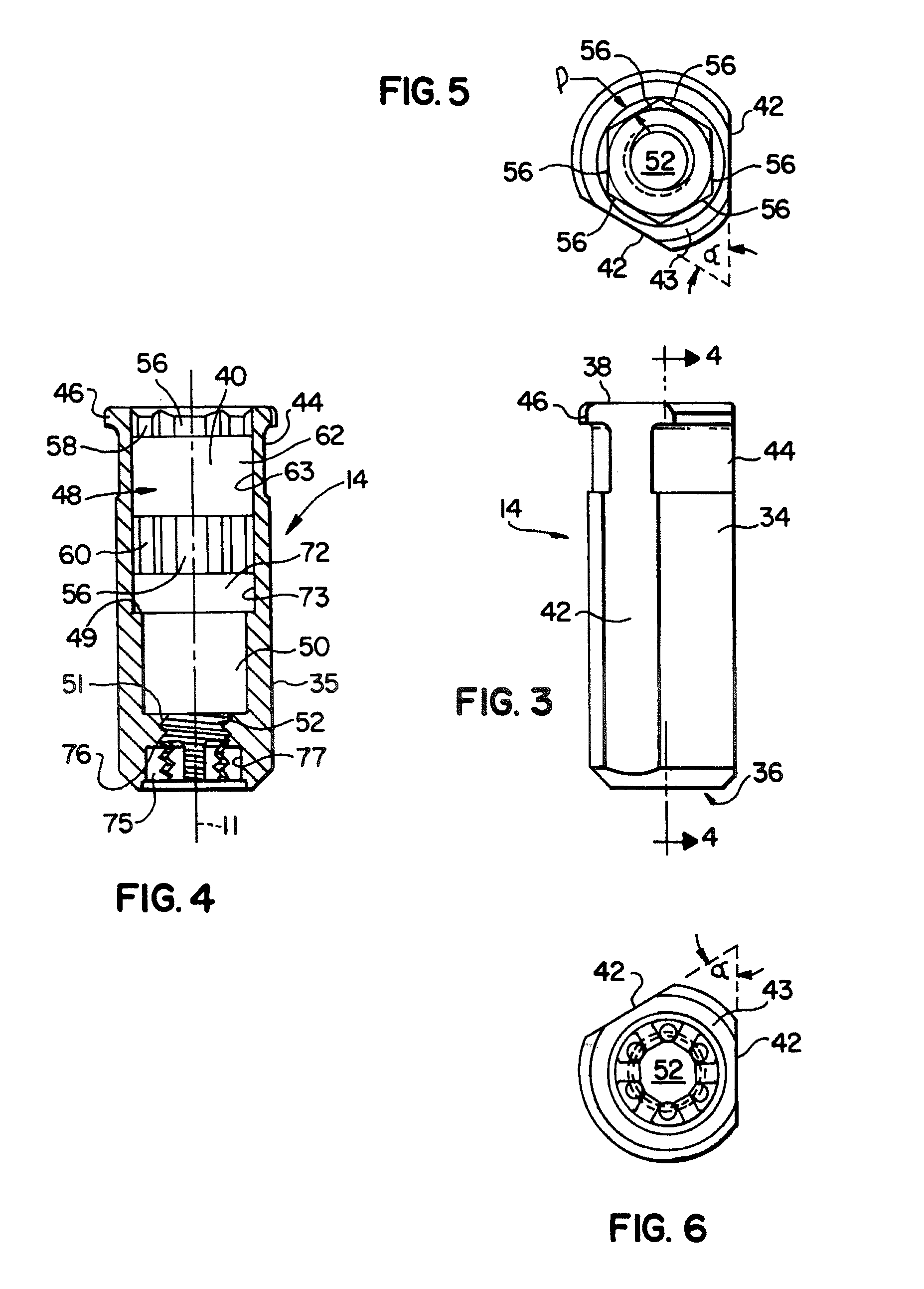
[0016]There is provided herein an apparatus and system for installing an implant into a prepared surgical site and limiting the applied torque to prevent the implant from being damaged. The system generally includes an implant, a drive tool for supplying rotational force to the implant, and a fixture mount that is disposed between and aligned with the implant and the drive tool, and that transmits the rotational force applied by the drive tool to the implant. Also disclosed is a method for installing the implant with the fixture mount and, thereafter, employing the fixture mount as an impression post and abutment for a temporary prosthesis.

[0017]According to a preferred embodiment of the invention, at least one end of the fixture mount includes an end portion that releasably engages the adjacent end of either the drive tool or the implant, as the case may be, and that is adapted to receive the applied torque and transmit it to the implant so long as the torque does not exceed a pred...


PUM


Abstract

The disclosed fixture mount limits torque that may be applied when installing a dental implant and also serves as an impression post and an abutment for a temporary prosthesis. In preferred embodiments, the fixture mount is formed of plastic and is subject to chair side modifications by the surgeon so as to be better suited as an abutment. Methods of shaping the fixture mount for use as an abutment and for making a dental restoration using the shaped abutment are disclosed.

Description

CROSS-REFERENCE TO RELATED APPLICATIONS[0001]This application claims the benefit of priority of U.S. Provisional Application Ser. No. 60 / 322,620, filed Sep. 17, 2001.BACKGROUND OF THE INVENTION[0002]1. Field of the Invention[0003]The present invention relates generally to the field of dental implantogy. More specifically, the invention relates to apparatus and methods allowing chair-side modifications to be made to components used in making dental restorations.[0004]2. Background Information[0005]Dental implants play an extraordinarily important role in modern dentistry. Implants serve as the foundation for a variety of dental prostheses as may be provided to correct debilitating or embarrassing conditions caused by, for example, disease, accident or natural aging.[0006]In order to adequately support the dental prosthesis for which it is intended, the implant (also referred to as a “fixture”) is surgically implanted into healthy bone tissue of the patient's alveolar (jaw) bone. To i...

Claims


Application Information

Patent Timeline
Patent Type & Authority Patents(United States)
IPC IPC(8): A61C8/00A61C1/18
CPCA61C8/0001A61C8/005A61C8/0066A61C8/0089A61C1/186A61C8/0054A61C8/0059A61C8/006A61C8/0068
Inventor GERVAIS, CHRISTOPHERBASSETT, JEFFERYPETTERSEN, CARL
Owner ZIMMER DENTAL INC
Why Eureka
Try Eureka