
Plastic-shell locking seal

A technology of sealing and plastic casing, which is applied in the direction of seals, stamps, instruments, etc., to achieve the effects of automation, improved work efficiency, and good security and anti-tampering performance

Inactive Publication Date: 2012-02-15
江门市大光明电力设备厂有限公司
View PDF1 Cites 2 Cited by
  • Summary
  • Abstract
  • Description
  • Claims
  • Application Information

AI Technical Summary

Problems solved by technology

However, since the self-locking molded case seal usually requires manual operation of threading the seal line, with the development of society, more and more electrical metering devices are used, and the work of the metering and verification department of the power supply bureau is also getting heavier. If the traditional manual operation of threading the seal line cannot meet the existing work requirements in terms of efficiency and personnel, some power supply departments have specially adopted fully automatic verification and automatic sealing equipment in order to improve work efficiency. In this way, For practical needs, it is imminent to develop a molded case lock that is convenient for automatic sealing operation

Method used


Image

  • Plastic-shell locking seal
  • Plastic-shell locking seal
  • Plastic-shell locking seal

Examples


Embodiment 1

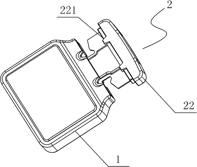
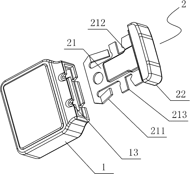
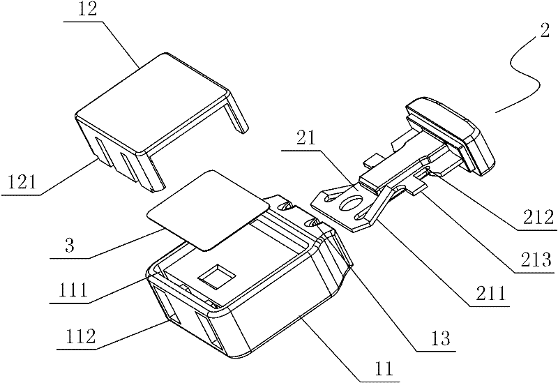
[0028] Such as figure 1 , figure 2 , Figure 4 As shown, the molded case lock of the present invention includes a lock housing 1 and an insert 2 mated with the lock housing 1. The insert 2 includes an elastic chip 21 and a The plug connector 22 placed outside the sealing shell, the elastic chip 21 is provided with two elastic barbs 211 inclined in opposite directions. To improve the convenience of operation; the elastic chip 21 is provided with a card slot 212 for accommodating the sealing wire, and in addition, a threading slot is provided at the end surface of the sealing housing 1 and the plug connector 22 where it fits.

[0029] Such as image 3 As shown, the sealing housing 1 includes a body 11 and a cover 12 mated with the body 11. The bottom of the cover 12 is provided with an insertion column 121, and the body 11 is provided with a socket for accommodating the insertion of the insertion column 121. In addition, the bottom of the body 11 is provided with a process ...

Embodiment 2

[0037] This embodiment is basically the same as the first embodiment above, the difference is: Figure 6 , Figure 7 As shown, the threading groove includes a first groove 16 placed in the sealing housing 1 and a second groove 222 placed in the plug connector 22, the first groove 16 and the second groove 222 are combined to form Threading trough, the effect of this threading trough is exactly the same as embodiment one, repeats it no longer here.

Embodiment 3

[0039] This embodiment is basically the same as the first and second embodiments above, the difference is that: Figure 8 As shown, the threading groove is a plug connector groove 223 placed on the plug connector 22 where it cooperates with the sealing housing 1. The function of the plug connector groove 223 is the same as that of the previous embodiments, and will not be repeated here.


PUM


Abstract

The invention belongs to the technical field of locking seals for electric metering devices, and particularly relates to a plastic-shell locking seal which is used on an automatic electric metering device calibration line. The plastic-shell locking seal comprises a locking seal shell and a plug suitably plugged in the locking seal shell, the plug comprises an elastic chip and a plugging head, the elastic chip is arranged in the locking seal shell, the plugging head is arranged outside the locking seal shell, the elastic chip is provided with elastic barbs, the inner wall of the locking seal shell is provided with steps for fastening the elastic barbs, threading notches are arranged at positions on the end surface of the locking seal shell, which are matched with the plugging head, and the elastic chip is provided with notches for holding a seal wire. The plastic-shell locking seal can effectively cooperate with the full-automatic sealing operation of an electric metering device, the threading process of the plastic-shell locking seal is simple and convenient, and moreover, the plastic-shell locking seal has good self-locking and anti-opening properties and high safety performance.

Description

technical field [0001] The invention belongs to the technical field of sealing of electrical metering devices. In particular, it relates to a molded case seal used on an automatic verification assembly line of an electrical metering device. Background technique [0002] In the prior art, in the field of sealing of electrical metering devices such as electric energy meters, the one-time self-locking molded case sealing has better anti-counterfeiting effect than the original lead-sealed seal, and is safer and more practical, so it has been widely used. Applications. However, since the self-locking molded case seal usually requires manual operation of threading the seal line, with the development of society, more and more electrical metering devices are used, and the work of the metering and verification department of the power supply bureau is also getting heavier. If the traditional manual operation of threading the seal line cannot meet the existing work requirements in te...

Claims


Application Information

Patent Timeline
Patent Type & Authority Applications(China)
IPC IPC(8): G09F3/03
Inventor 欧明卫李仕奇杨宏仓林岳凌梁健文
Owner 江门市大光明电力设备厂有限公司
Learn More