Plate rolling machine

A plate rolling machine and roll rolling technology, which is applied in the direction of mechanical equipment, belts/chains/gears, transmission devices, etc., can solve the problems that the center roll cannot be made too thin, work efficiency is low, and it is troublesome to take out workpieces, etc., to achieve production efficiency Improvement, reliable performance, and improved manufacturing accuracy

Inactive Publication Date: 2014-04-02
WEICHAI HEAVY MACHINERY CO LTD
View PDF8 Cites 0 Cited by
  • Summary
  • Abstract
  • Description
  • Claims
  • Application Information

AI Technical Summary

Problems solved by technology

Due to the presence of the driven shaft, material slippage is prone to occur during the rolling process
Especially when dealing with thin workpieces, the corresponding friction force is small, the operation is very difficult, and the work efficiency is low
[0006] In addition, for the plate rolling machine in the prior art, it is very troublesome to take out the workpiece after the workpiece is rolled, because the two ends of the center roll (that is, the upper roll) are closed, and one end of the center roll needs to be pressed first. Hold the other end in the air, and then open the complex door mechanism fixedly supported by the end of the winding roller, and the workpiece can be taken out
In addition, limited by the rigidity of the roll itself, the center roll cannot be made too thin, so that the workpiece can only be rolled into cylinder

Method used


Image

  • Plate rolling machine
  • Plate rolling machine
  • Plate rolling machine

Examples


Embodiment Construction

[0018] The present invention will now be described with reference to the drawings, wherein like reference numerals designate like or similar devices throughout.

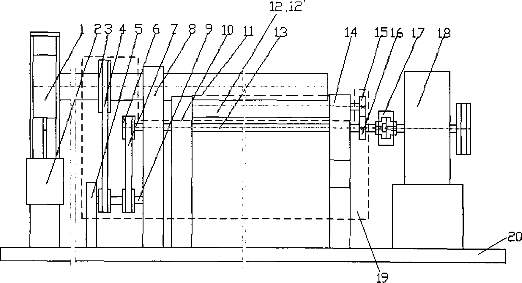
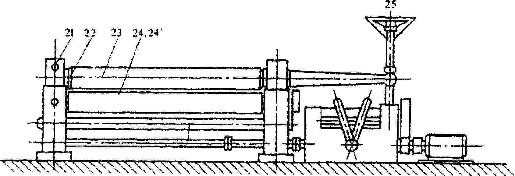
[0019] figure 1 is a schematic front view of the structure of the plate bending machine according to the preferred embodiment of the present invention. In this preferred embodiment, the plate rolling machine of the present invention realizes all active drives of the three winding rollers (the upper winding roller and the first and second lower winding rollers) while realizing the open structure. and figure 2 The plate rolling machine shown in the prior art is similar, figure 1 The plate rolling machine of the present invention shown also includes a frame 20, an upper roll 11 mounted on the frame, a first lower roll 12 and a second lower roll 12'. Similar to the prior art, the plate bending machine of the present invention may also include a speed reducer 17 . The specific implementation of this preferred embodi...


PUM


Abstract

The invention provides a plate rolling machine. The machine comprises a bracket, an upper winding up roller, a first lower winding up roller, a second lower winding up roller and a pneumatic device, wherein the upper winding up roller, the first lower winding up roller and the second lower winding up roller are installed on the bracket and are all drive winding up rollers; the first end of the upper winding up roller is of an open structure; and the pneumatic device is connected with the second end of the upper winding up roller and is used for controlling the open structured first end of the upper winding up roller to be lifted.

Description

technical field [0001] The present invention relates generally to plate rolling machines and, more particularly, to a three roll plate rolling machine. Background technique [0002] figure 2 It is a schematic diagram of the structure of the plate bending machine in the prior art. Such as figure 2 As shown, the plate rolling machine includes a support 22, an upper roll 23 mounted on the support, a first lower roll 24 and a second lower roll 24'. The plate bending machine in the prior art also includes a motor and a reducer. The working process of the plate bending machine is as follows: the first lower winding roller 24 and the second lower winding roller 24' are driven by a transmission device to rotate in the same direction at the same speed, or rotate in the opposite direction. Due to the friction between the first lower winding roller 24 and the second lower winding roller 24' and the workpiece respectively, the workpiece is driven to move forward and the driven rotat...

Claims


Application Information

Patent Timeline
Patent Type & Authority Patents(China)
IPC IPC(8): B21D5/14F16H37/02
Inventor 刘新胜刘建新李成吉王洪波
Owner WEICHAI HEAVY MACHINERY CO LTD
Why Eureka
Try Eureka