
Pyroelectric detector, pyroelectric detection device and electronic instrument

A technology of electronic equipment and detection devices, applied in the field of pyroelectric detectors

Active Publication Date: 2012-03-07
SEIKO EPSON CORP
View PDF8 Cites 0 Cited by
  • Summary
  • Abstract
  • Description
  • Claims
  • Application Information

AI Technical Summary

Problems solved by technology

However, heat from the capacitor ma

Method used


Image

  • Pyroelectric detector, pyroelectric detection device and electronic instrument
  • Pyroelectric detector, pyroelectric detection device and electronic instrument
  • Pyroelectric detector, pyroelectric detection device and electronic instrument

Examples


Embodiment Construction

[0037] Next, preferred embodiments of the present invention will be described in detail. In addition, the present embodiment described below does not unreasonably limit the content of the present invention described in the claims, and all the configurations described in the present embodiment are not necessarily essential as the solution means of the present invention.

[0038] 1. Pyroelectric infrared detection device

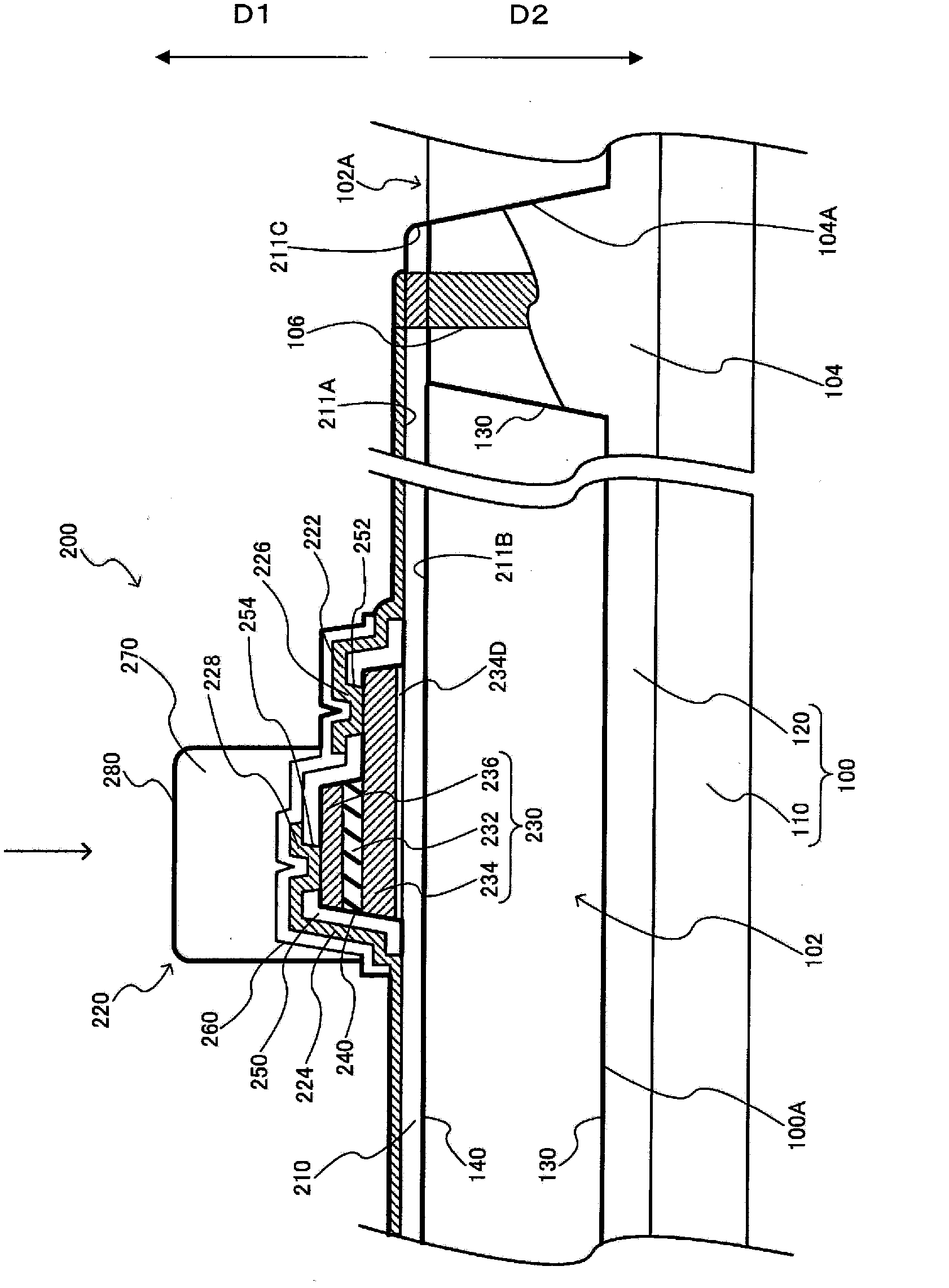
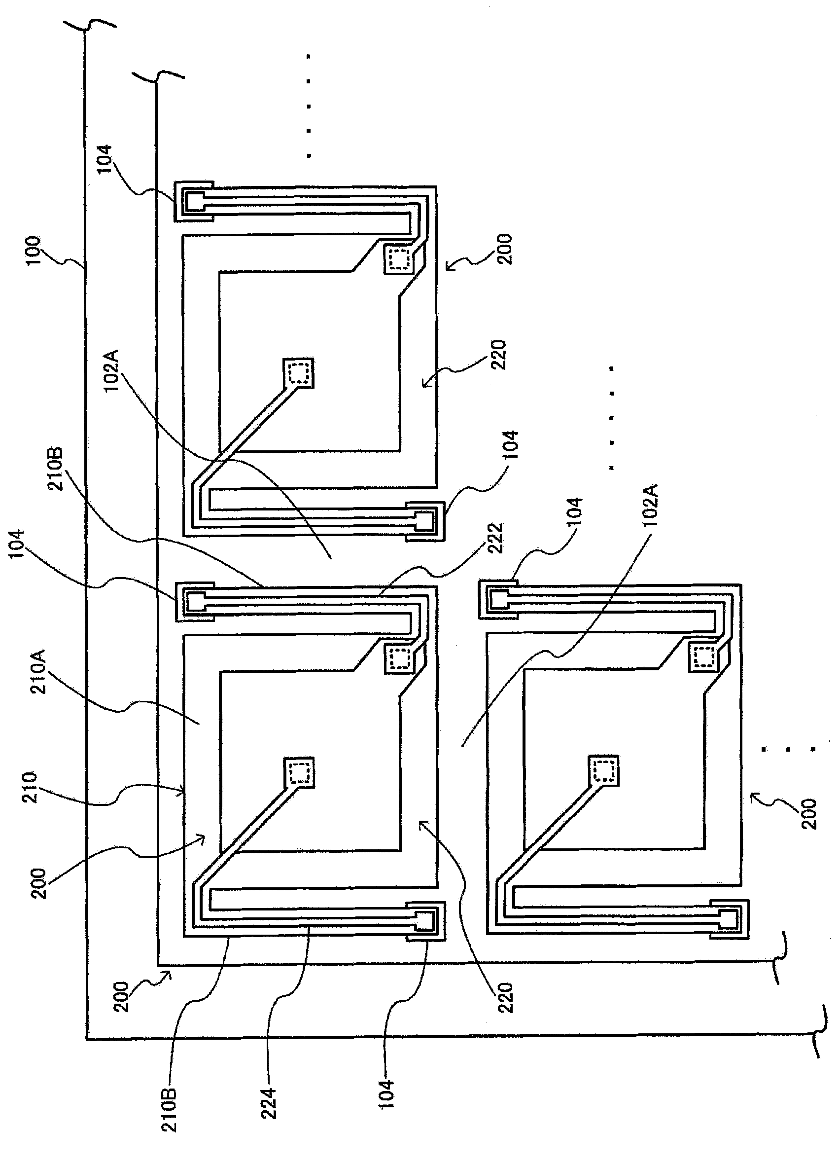
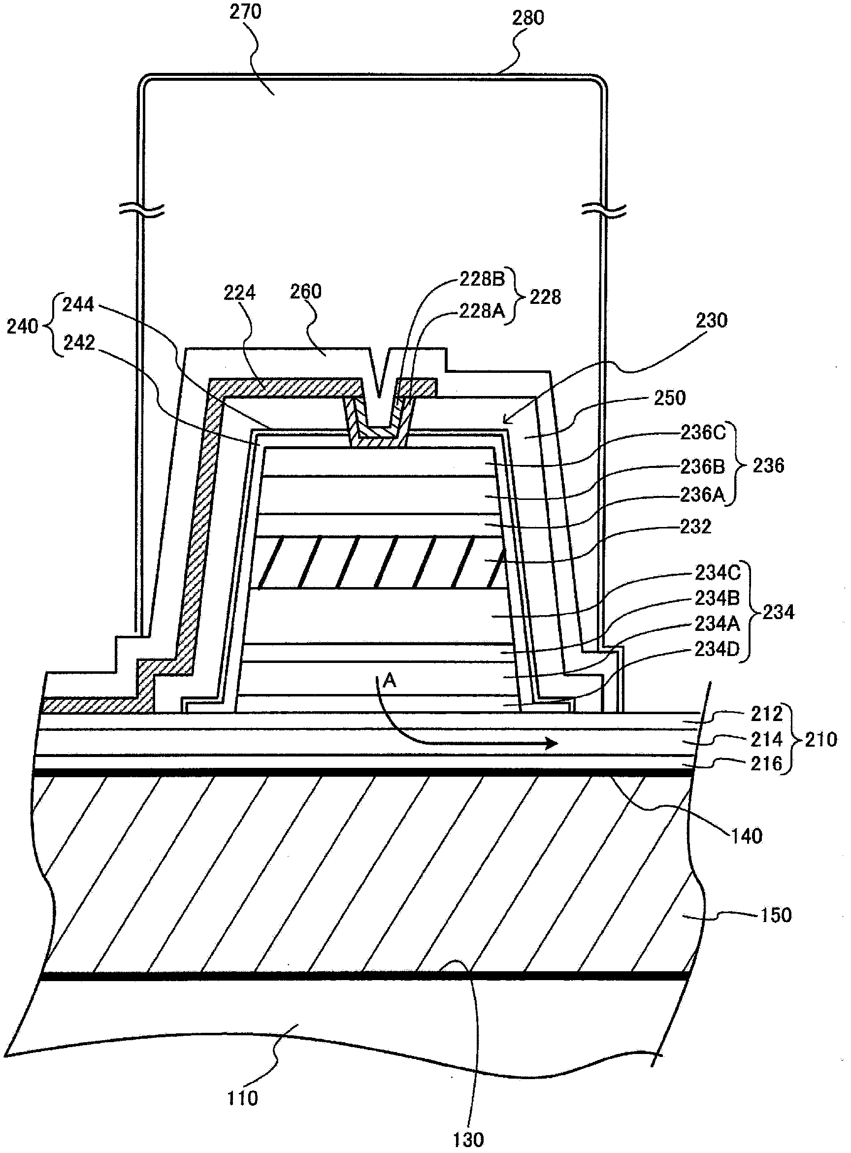
[0039] figure 2 Shown is a pyroelectric infrared detection device (in a broad sense, a pyroelectric detection device) in which a plurality of units of pyroelectric infrared detectors 200 are arranged in biaxial directions, for example, orthogonal biaxial directions. type infrared detector 200 are equipped with figure 1 The supporting member 210 and the pyroelectric detection element 220 mounted thereon are shown. In addition, it is also possible to configure the pyroelectric infrared ray detection device with only one unit of pyroelectric infrared ray dete...


PUM

PropertyMeasurementUnit
Surface roughnessaaaaaaaaaa

Abstract

The invention provides a pyroelectric detector, a pyroelectric detection device and an electronic instrument. The pyroelectric detector includes a pyroelectric detection element, a support member and a support part. The pyroelectric detection element has a capacitor including a first electrode, a second electrode, and a pyroelectric body. The support member includes first and second sides with the pyroelectric detection element being mounted on the first side and the second side facing a cavity. The support part, the support member, and the pyroelectric detection element are laminated in this order in a first direction with the cavity being formed between the support part and the support member. The support member has at least a first insulation layer on the first side contacting the first electrode, with the first insulation layer having a hydrogen content rate smaller than a hydrogen content rate of a second insulation layer positioned further in a second direction than the first insulation layer, the second direction being opposite the first direction.

Description

technical field [0001] The present invention relates to a pyroelectric detector, a pyroelectric detection device, electronic equipment and the like. Background technique [0002] As a pyroelectric detection device, a pyroelectric type or a bolometer type infrared detection device is known. The infrared detection device uses the phenomenon that the spontaneous polarization of pyroelectric components changes with the amount of infrared light (temperature) received (pyroelectric effect or pyroelectric effect), and generates electromotive force (polarization) at both ends of the pyroelectric body. Generated electric charge) (pyroelectric type), or changes resistance value according to temperature (bolometer type), thereby detecting infrared rays. Compared with the bolometer-type infrared detection device, the pyroelectric infrared detection device has an advantage of high detection sensitivity although the manufacturing process is complicated. [0003] A cell of a pyroelectric...

Claims


Application Information

Patent Timeline
IPC IPC(8): G01J5/34
CPCG01J5/02G01J5/024G01J5/04G01J5/046G01J5/08G01J5/0853G01J5/34G01J5/068H10N15/10
Inventor 野田贵史
Owner SEIKO EPSON CORP
Learn More