
Accelerated b1 mapping

A technique for mapping data, radio frequency emission, applied in the fields of medical magnetic resonance imaging and spectroscopy, which can solve problems such as prolonged imaging session time

Active Publication Date: 2012-03-07
KONINK PHILIPS ELECTRONICS NV
View PDF3 Cites 2 Cited by
  • Summary
  • Abstract
  • Description
  • Claims
  • Application Information

AI Technical Summary

Problems solved by technology

Unfortunately, these B 1 Launch field mapping MR sequences are relatively slow and undesirably lengthen the imaging session

Method used


Image

  • Accelerated b1 mapping
  • Accelerated b1 mapping
  • Accelerated b1 mapping

Examples


Embodiment Construction

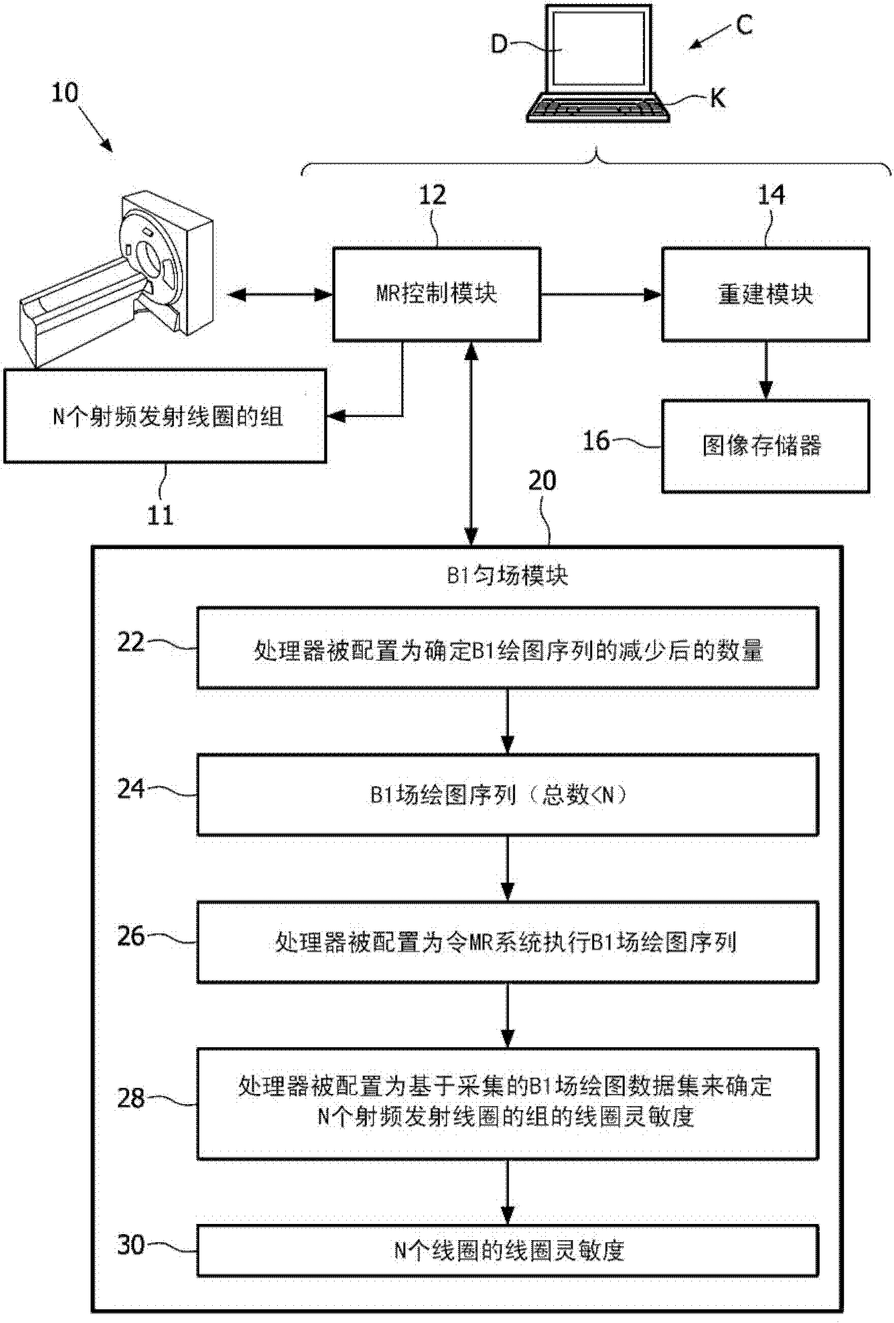
[0015] refer to figure 1 , the imaging system includes a magnetic resonance (MR) scanner 10, such as the illustrated Achieve TM Magnetic resonance scanner (obtained from Royal Philips Electronics, Eindhoven, The Netherlands), or Intera TM or Panorama TM Magnetic resonance scanner (both also available from Royal Philips Electronics), or another commercially available magnetic resonance scanner, or a non-commercial magnetic resonance scanner, etc. In a typical embodiment, the magnetic resonance scanner includes internal components (not shown), such as generating a static magnetic field (B 0 ) of a superconducting or resistive main magnet and a set of magnetic field gradient coil windings for superimposing a selected magnetic field gradient on the static magnetic field.

[0016] The MR scanner also comprises or operates in conjunction with a set of radio frequency transmit coils 11 , the number of which is N. For example, the radio frequency transmit coil set 11 may be an arr...


PUM


Abstract

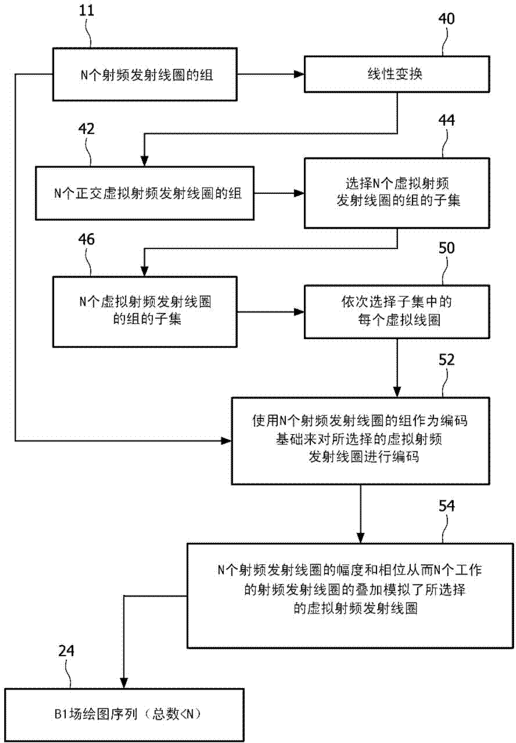
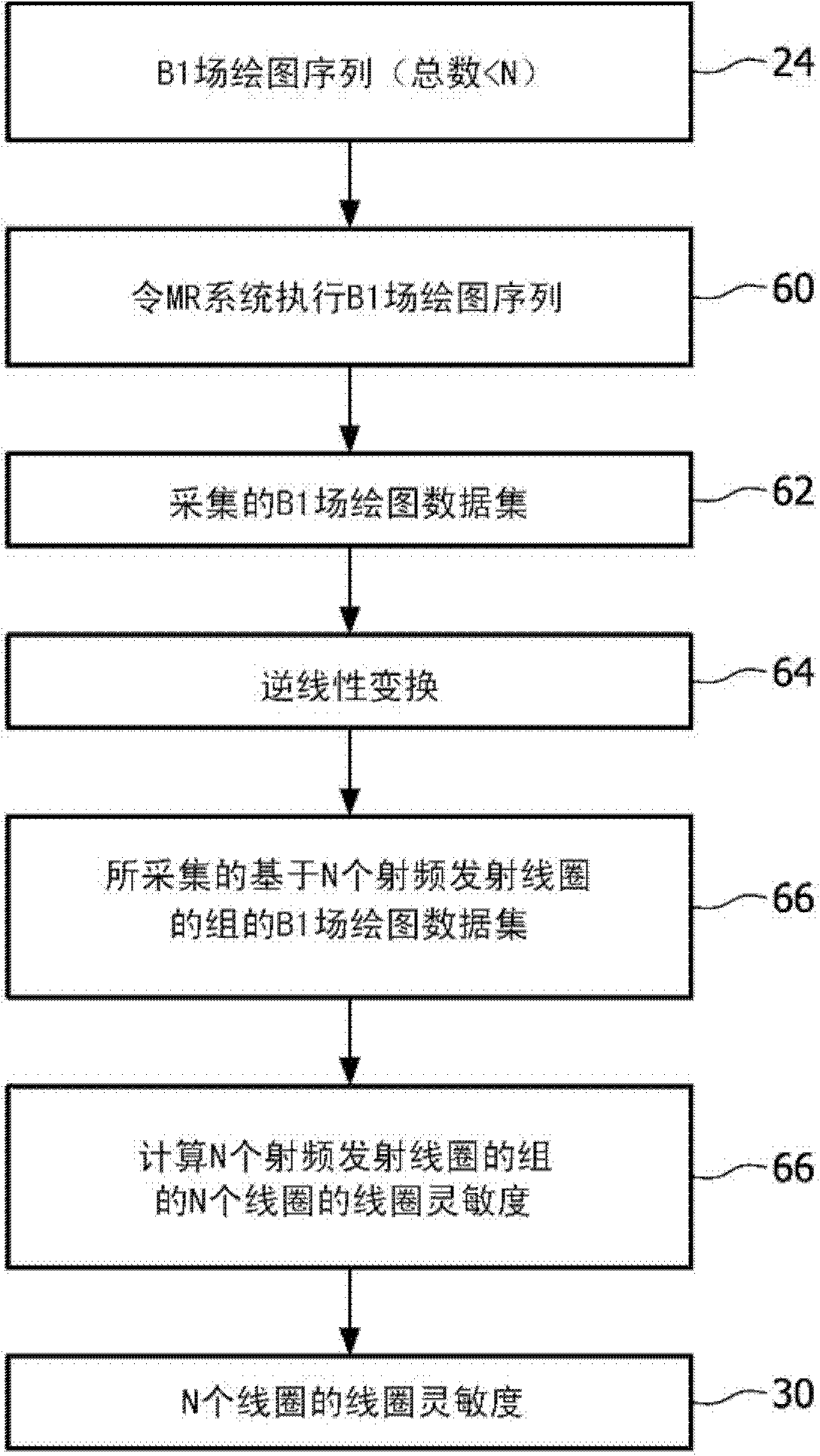
A method comprises: performing a number of B i field mapping sequences (24) using a set of radio frequency transmit coils (11) to acquire a B1 field mapping data set wherein said number is less than a number of radio frequency transmit coils in the set of radio frequency transmit coils; and determining coil sensitivities (30) for the set of radio frequency transmit coils based on the acquired B1 field mapping data set. In some embodiments, the performed B1 field mapping sequences are defined by (i) performing a linear transform (40) on the set of radio frequency transmit coils to generate a set of orthogonal virtual radio frequency transmit coils (42) and (ii) selecting (44) a sub- set (46) of the set of orthogonal virtual radio frequency transmit coils that define the performed B1 field mapping sequences.

Description

technical field [0001] The following relates to the field of magnetic resonance, the field of magnetic resonance imaging, the field of magnetic resonance spectroscopy, the field of medical magnetic resonance imaging and spectroscopy, and related fields. Background technique [0002] Magnetic resonance (MR) image quality depends on B 1 Uniformity of the launch field. For this purpose, the RF coils used for magnetic field excitation are designed to generate a substantially uniform B over the entire field of view (FOV). 1 launch site. This can be achieved by using multiple RF transmit coils or an array of RF transmit coils each strategically placed at the FOV to collectively generate a substantially uniform B across the FOV. 1 launch site. However, this design has disadvantages. Also, designed to be uniform under no-load condition B 1 The emission field can be distorted by the magnetic susceptibility of the object. This is the so-called object loading effect, and this ef...

Claims


Application Information

Patent Timeline
Patent Type & Authority Applications(China)
IPC IPC(8): G01R33/32G01R33/58
CPCG01R33/246G01R33/5612G01R33/5659G01R33/583G01R33/586
Inventor P·博尔纳特K·内尔克
Owner KONINK PHILIPS ELECTRONICS NV
Learn More