Multi-beam plate leveller

A leveling machine and plate technology, applied in the field of forging equipment, can solve the problems of poor lateral force resistance of rollers and upper beams, unusable, limited beam width, etc., and achieve the effect of improving the leveling quality.

Inactive Publication Date: 2012-03-14
潘耀华 +1
View PDF6 Cites 7 Cited by
  • Summary
  • Abstract
  • Description
  • Claims
  • Application Information

AI Technical Summary

Problems solved by technology

Since the upper beam is a whole, and the work roll and the backup roll are installed on it, it involves the flatness of the upper beam, the accumulation error of the processing of the work roll and the backup roll, so that the flatness of the upper and lower rolls is difficult to achieve an ideal state.
[0003] The other is a single-girder leveling machine. Its Chinese patent number is: ZL2000420001178.X. Their upper beams use multi-piece upper beams. There are support rolls above the work rolls, and a separate upper beam above the support rolls. , the center distance of the upper roller is positioned by the bearing seat of the upper roller, and there is a certain gap between the beam and the beam, but due to the limited width of the beam, the ability of the roller and the upper beam to resist lateral force is poor, although its leveling accuracy is better than that of the whole The beam is much better, but its leveling is not optimal due to the large deflection in the lateral direction (in and out)
For sheet leveling machines, the beams and work rolls are thinner, and the beams and work rolls basically have no rigidity against lateral force, so this structure cannot be used in sheet metal

Method used


Image

  • Multi-beam plate leveller
  • Multi-beam plate leveller
  • Multi-beam plate leveller

Examples


Embodiment Construction

[0028] The present invention will be further described in conjunction with the accompanying drawings.

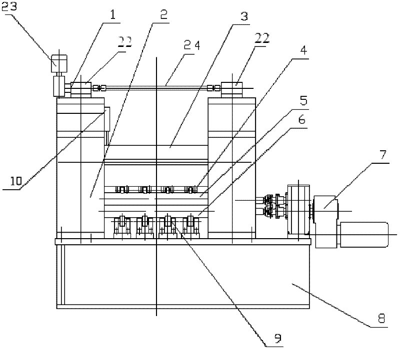
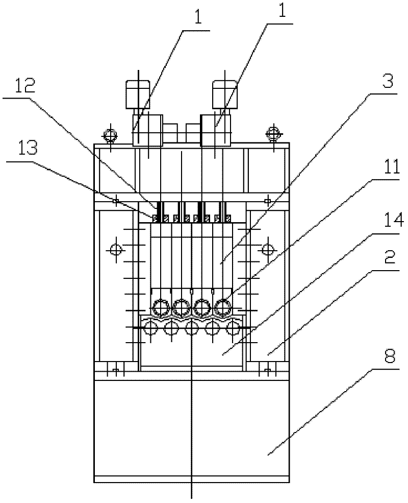
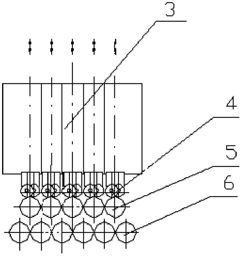
[0029] like figure 1 , 2 Shown: a multi-beam plate leveler, which includes a pressing mechanism 1, a frame 2, a single beam 3, an upper support roll 4, an upper work roll 5, a lower work roll 6, a main drive 7, and a bed 8 , the lower backup roll 9, the displacement measuring device 10, the upper roll bearing housing 11, the lower rolling bearing housing 14; Multiple sets of upper back-up rolls 4 are installed between the sheet beam 3 and the upper work roll 5, and all of them are arranged in a staggered manner. Each set of pressing mechanism 1 is composed of two screw rods 12, two nuts 13, two reducers 22, A driving motor 23 and a set of shaft coupling 24 are formed, and two speed reducers 22 of all pressing mechanisms are installed on the frame 2, and the driving motor 23 is directly connected with one of the speed reducers 22, and the two speed reducers 22 are connected...


PUM


Abstract

The invention relates to a multi-beam plate leveler, which is structurally characterized in that all screwdown mechanisms are installed on a rack; each set of screwdown mechanism is connected to two upper sides of two sides of each single beam respectively by a screw and a nut; two ends of each upper working roll are respectively fixed on one single beam by an upper roll bearing pedestal; a plurality of sets of upper support rolls are fixed on each single beam; at least one set of support roll is symmetrically arranged or staggered; the single beams are mutually, laterally and rigidly supported in the rack; the single beam on the outer side is thicker and has enough lateral rigidity; a bed body and the rack are fixedly connected; two ends of each lower working roll are respectively fixed on the bed body by a lower roll bearing pedestal; a plurality of sets of lower support rolls are fixed on the bed body; each lower working roll needs to be supported by multiple sets of lower support rolls; a main drive is respectively connected with the upper working roll and the lower working roll by a coupler; and each single beam is provided with a displacement measurement device. The multi-beam plate leveler has the advantages of strong lateral rigidity of the single beams, capability of realizing thin plate leveling and wide application range.

Description

technical field [0001] The invention relates to a forging equipment used for processing metal plates, in particular to a multi-beam plate leveling machine. Background technique [0002] Existing plate leveling machines are mostly a leveling machine in which the integral beam is pressed down as a whole. Whether it is on the leveling production line of a steel plant, or an ordinary uncoiling production line, or a stand-alone machine, most of their levelers use integral The upper beam structure changes the opening of each upper work roll and lower work roll through the up and down movement and inclination of the upper beam to meet the leveling process requirements of different plate thicknesses. Since the upper beam is a whole, and the work roll and the back-up roll are installed on it, the accumulation error involving the flatness of the upper beam, the processing of the work roll and the back-up roll makes it difficult for the flatness of the upper and lower rolls to reach an...

Claims


Application Information

Patent Timeline
Patent Type & Authority Applications(China)
IPC IPC(8): B21D1/02
Inventor 潘耀华王一强
Owner 潘耀华
Why Eureka
Try Eureka