Charging control method, charging monitoring control center and vehicle-mounted navigation device of electric automobile

A charging control method and technology for electric vehicles, which can be applied to electric vehicle charging technology, electric vehicles, battery circuit devices, etc., and can solve problems such as power quality degradation in power distribution systems

Active Publication Date: 2012-03-14
HITACHI LTD
View PDF5 Cites 33 Cited by
  • Summary
  • Abstract
  • Description
  • Claims
  • Application Information

AI Technical Summary

Problems solved by technology

Specifically, there is concern that with the spread of fully electrified houses and the introduction of a large number of electric vehicles, various loads will be placed on the power supply system, resulting in the increase of uncertain loads for charging electric vehicles. Power quality degradation of power distribution system, etc.

Method used


Image

  • Charging control method, charging monitoring control center and vehicle-mounted navigation device of electric automobile
  • Charging control method, charging monitoring control center and vehicle-mounted navigation device of electric automobile
  • Charging control method, charging monitoring control center and vehicle-mounted navigation device of electric automobile

Examples


no. 1 approach

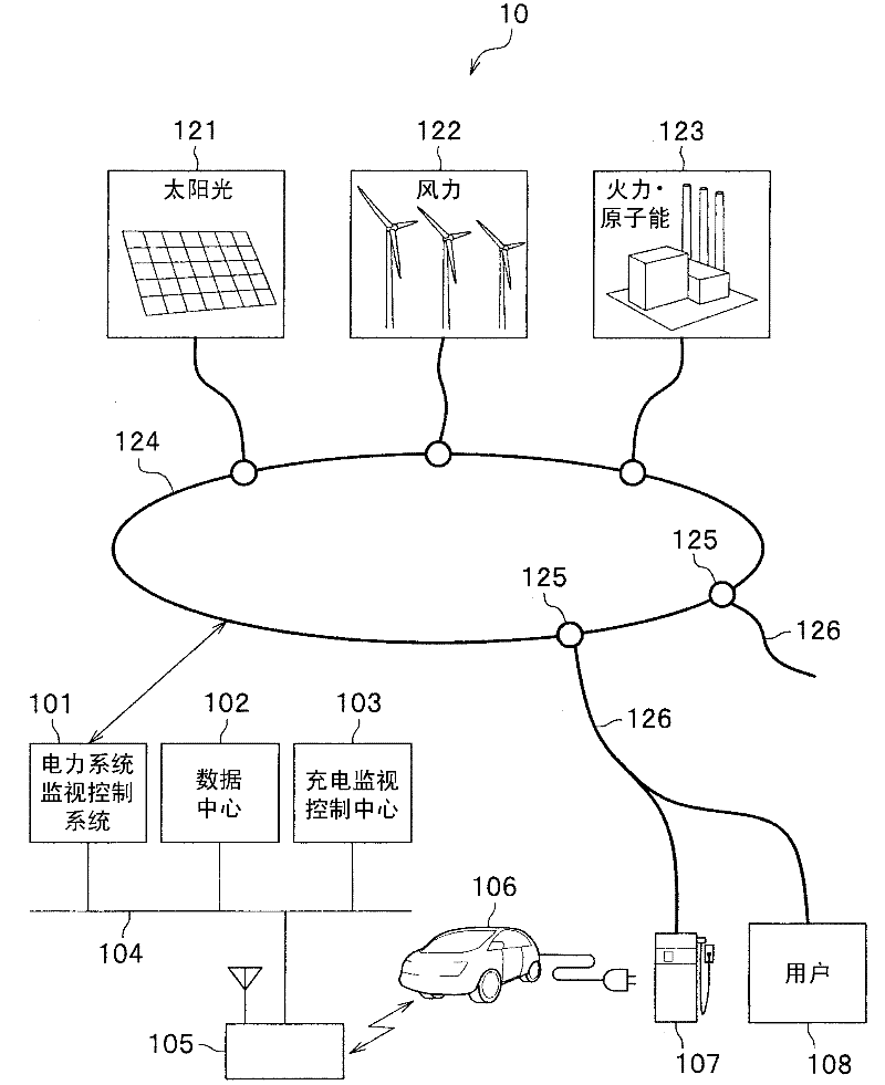
[0049] figure 1 It is an overall configuration diagram of the power system stabilization system according to the first embodiment of the present invention. figure 1 The power system stabilization system 10 shown is a system for stabilizing the power quality of a power system 124, wherein the power system 124 will be converted from large-scale power supply equipment 123 based on thermal power stations and nuclear power stations. The power provided by the solar power generation equipment 121 and the wind power generation equipment 122 is distributed to the charging station 107 and the user 108 via the power distribution substation 125 and the transmission line 126 . Here, in the charging station 107, in addition to the existing dedicated equipment such as gasoline stations, it also includes simple equipment installed in parking lots of commercial facilities and metered toll parking lots. Large users such as commercial and industrial facilities and general households.

[0050] ...

no. 2 approach

[0116] In the second embodiment, an example will be described in which user loads based on all-electric equipment and charging power for EVs are controlled for each power distribution area of ​​a local production and local consumption unit where a charging monitoring control center is installed. This is done by adding the above-mentioned first embodiment Figure 7 The processing shown is replaced by Figure 19 In the process shown, the user's load is controlled while utilizing the renewable energy based on the solar power generation facility, and the stabilization of the power quality in the power distribution area of ​​the local production and local consumption unit is realized.

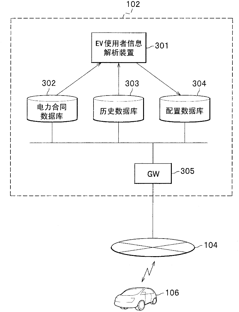
[0117] Figure 18 It is a block diagram showing a device configuration example of the data center 102A in the second embodiment. like Figure 18 As shown, the structure of the data center 102A is, in image 3 A user database 306 is added to the data center 102 of the first embodiment shown. In ...

no. 3 approach

[0130] In the third embodiment, an example will be described in which the charging monitoring control center authenticates the EV charged at the charging station, and the accounting center automatically performs accounting and settlement processing of the charging fee. Figure 21 It is an overall configuration diagram of a power system stabilization system according to a third embodiment of the present invention. like Figure 21 As shown, the structure of the power system stabilization system 10A is, in figure 1 An authentication center 109 and an accounting center 110 are added to the power system stabilization system 10 according to the first embodiment shown.

[0131] Authentication center 109 has a function of authenticating EV 106 that charging monitoring control center 103 communicates via communication network 104 . This certification center 109 is operated by a power company or a provider that provides power-related services, or a provider that provides certification...


PUM


Abstract

The present invention provides a charging control method, charging monitoring control center and vehicle-mounted navigation device of electric automobiles. For obtaining the balance of supply and demand of electricity in an electric system, needed electric automobiles are guided to charging stations in needed time, and the charging of the electric automobiles of the charging stations can be controlled. For distributing total charging electricity consumed by the charging stations within electricity distribution areas planned by an electricity system monitoring control system to the electric automobiles charged by the charging stations to consume, the charging monitoring control center is used for collecting the electric automobiles charged in the charging stations for driving electric automobiles, and through distributing the total charging electricity to the chosen electric automobiles from the collected electric automobiles, charging amount giving to the electric automobiles can be decided. The electric automobiles are respectively guided to the charging stations, and the charging electricity of the electric automobiles of the charging stations are respectively controlled.

Description

technical field [0001] The present invention relates to a technique for stabilizing power quality of an electric power system by controlling the amount of charge given to an electric vehicle. Background technique [0002] In recent years, the demand for energy saving and cost saving has greatly increased. In November 2007, in the Energy Conservation Sector Policy Subcommittee of the General Resources and Energy Research Council, an advisory body for the Ministry of Economy and Industry, we learned about the revision of the Energy Conservation Law (Revision of the Energy Conservation Law), which was considered for the achievement of the greenhouse gas reduction target for the Kyoto Protocol. Report, on December 12 of the same year, the department also understood and sorted out the final report. [0003] According to this report, energy conservation is one of the most important issues as the basis of national life and economic activities for our country, which relies on overs...

Claims


Application Information

Patent Timeline
Patent Type & Authority Applications(China)
IPC IPC(8): H02J7/00B60L11/18G01C21/34
CPCY02T90/16Y04S30/12Y02T10/70Y02T90/167
Inventor 友部修富田泰志石田隆张富田民则渡边雅浩
Owner HITACHI LTD
Why Eureka
Try Eureka