
Uplink and downlink transmission system based on single-wavelength orthogonal frequency division multiple access (OFDMA) passive optical network

A passive optical network and transmission system technology, applied in the field of uplink and downlink transmission systems based on single-wavelength OFDMA passive optical network, can solve the problems of increasing the cost of optical line terminals, increasing the cost of optical network units, and not fully utilizing optical carrier resources. , to achieve the effects of improving spectrum utilization, saving costs, and saving wavelength resources

Active Publication Date: 2014-04-30
SHANGHAI JIAO TONG UNIV SUBEI RES INST
View PDF4 Cites 0 Cited by
  • Summary
  • Abstract
  • Description
  • Claims
  • Application Information

AI Technical Summary

Problems solved by technology

However, this solution uses two separate light sources at the optical line terminal as the local oscillator light source for heterodyne coherent detection, which increases the cost of the optical line terminal to a certain extent, and does not make full use of the resources of the optical carrier, thus to a certain extent On the other hand, the passive optical network system loses the advantage of low cost, and the optical network unit (ONU) uses a radio frequency source to up-convert the baseband OFDM signal. The use of radio frequency sources will also increase the cost of the optical network unit (ONU)

Method used


Image

  • Uplink and downlink transmission system based on single-wavelength orthogonal frequency division multiple access (OFDMA) passive optical network

Examples


Embodiment Construction

[0025] The embodiments of the present invention will be described in further detail below in conjunction with the accompanying drawings, but the present embodiments are not intended to limit the present invention, and any similar structures and similar changes of the present invention should be included in the protection scope of the present invention.

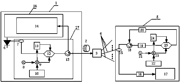
[0026] Such as figure 1 As shown, an uplink and downlink transmission system based on a single-wavelength OFDMA passive optical network provided by an embodiment of the present invention includes an optical line terminal 1, a remote node 3 and a plurality of optical network units 5;

[0027] The optical line terminal 1 includes a laser 6 for generating an optical carrier signal, a data modulation unit 27 for modulating an OFDM downlink signal, and an uplink data receiving unit 26 for demodulating an OFDM uplink signal;

[0028] It is characterized in that: the remote node 3 is an optical splitter combiner;

[0029]The data mo...


PUM


Abstract

The invention discloses an uplink and downlink transmission system based on a single-wavelength orthogonal frequency division multiple access (OFDMA) passive optical network, relates to the technical field of optical communication and aims to reduce the system cost and increase the frequency spectrum utilization rate. The system comprises an optical line terminal, a far-end node and a plurality of optical network units, wherein optical line terminal comprises a laser, a data modulation unit and an uplink data receiving unit; the data modulation unit is used for modulating a downlink signal onto a lower sideband of an optical carrier signal generated by the laser; the uplink data receiving unit is used for demodulating an uplink signal; the far-end node is used for distributing a modulated downlink signal to the optical network units and forwarding modulated uplink signals output by the optical network units to the optical line terminal; and the optical network units demodulate the modulated downlink signal, separate out an optical carrier from the modulated downlink signal, modulate the uplink signals onto an upper sideband of the separated optical carrier and send the uplink signals to the far-end node. The system cost of the system is low.

Description

technical field [0001] The invention relates to optical communication technology, in particular to a technology based on a single-wavelength OFDMA passive optical network uplink and downlink transmission system. Background technique [0002] Passive Optical Network (PON), as a low-cost solution to fiber-to-the-home access terminals, is the mainstream direction of current access network technology research. [0003] Traditional asynchronous transfer mode passive optical network (ATM Passive Optical Network, APON), Ethernet passive optical network (Ethernet Passive Optical Network, EPON) and Gigabit Passive Optical Network (Gigabit Passive Optical Network, GPON) technologies are all The time-division multiple access technology adopted, the bandwidth is shared by users, and complex scheduling algorithms and framing techniques are required to support different types of services. Although the emerging Wavelength-Division-Multiplexing Passive Optical Network (WDM-PON) technology ...

Claims


Application Information

Patent Timeline
Patent Type & Authority Patents(China)
IPC IPC(8): H04L27/26H04L5/00H04J14/02H04B10/25H04Q11/00
Inventor 王立肖石林毕美华周钊史杰
Owner SHANGHAI JIAO TONG UNIV SUBEI RES INST
Learn More