
Sublimator

A sublimator and inner shell technology, applied in the field of sublimers, can solve the problems of affecting the sublimation speed, shortening the service life of the sublimator, large energy consumption, etc., and achieve the effects of improving energy utilization, reducing heat loss, and improving sublimation speed.

Inactive Publication Date: 2012-03-21
苏州华微特粉体技术有限公司
View PDF8 Cites 0 Cited by
  • Summary
  • Abstract
  • Description
  • Claims
  • Application Information

AI Technical Summary

Problems solved by technology

[0003] The existing ordinary sublimator generally wraps the heating element outside the container. Although some sublimators have a stirring device inside, the material to be sublimated is added to the container at one time. As the sublimation process proceeds, the non-sublimable impurities And the unsublimated material is still very easy to harden in the container, so the heating temperature has to be continuously increased as the sublimation process proceeds, and the energy consumption is relatively large. Even if the heating temperature rises very high, it cannot make up for the increase in thermal resistance, which greatly affects Reduce the sublimation speed, and lead to damage to equipment components or reduce the service life of the sublimator. At the same time, the heating element is wrapped outside the container, so the heat loss is large and the utilization rate is not high.

Method used


Image

  • Sublimator
  • Sublimator
  • Sublimator

Examples


Embodiment Construction

[0021] Embodiments of the present invention will be further described below in conjunction with the accompanying drawings.

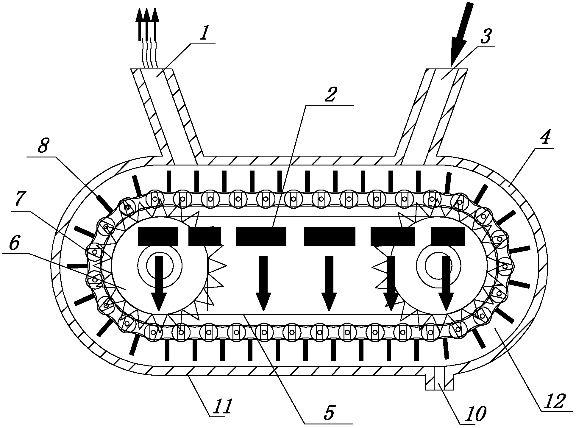
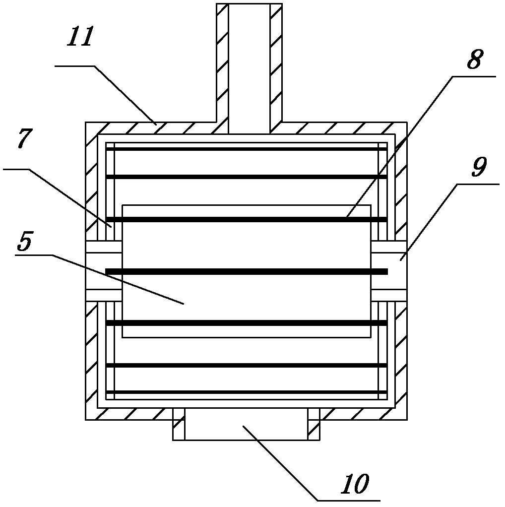
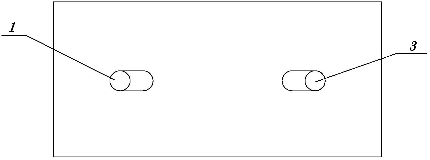
[0022] like figure 1 , figure 2 , image 3 As shown, a sublimator includes an inner shell 5 wrapping the heating element 2 and an outer shell 11 wrapping the inner shell 5. The outer shell 11 has a material inlet 3 and a material sublimation gas outlet 1, and the inner shell 5 and the outer shell 11 form a An annular passage 12 containing materials to be sublimed, and a transmission mechanism for making the materials to be sublimated flow along the annular passage is provided in the annular passage 12 . The transmission mechanism in this embodiment includes a bearing 9, a gear 6, a chain 7, and a shovel 8 for shoveling and stirring materials to be sublimated, such as figure 1 As shown, corrosion-resistant and high-temperature-resistant metal bearings 9 are respectively installed on the left and right sides of the front / rear end faces of the inner she...


PUM


Abstract

The invention provides a sublimator which is suitable for utilizing sublimation property of material to prepare chemicals and has the advantages as follows: the sublimation speed is high, the production efficiency is high, material cannot be hardened during the sublimation process, and energy utilization ratio is improved greatly. The sublimator comprises an inner housing and an outer housing, wherein, heating elements are coated with the inner housing; the inner housing is coated with the outer housing; a material filling port and a material sublimation gas outlet are formed on the outer housing; a ring-shaped channel used for holding material to be sublimated is formed between the inner housing and the outer housing; a transmission mechanism that leads the material to be sublimated to flow along the ring-shaped channel is arranged in the ring-shaped channel; the transmission mechanism comprises bearings, gears, chains and shovel plates; the shovel plates are used for shoveling and stirring material to be sublimated; transmission chains that surround the outer side surface of the inner housing in the circumferential direction are respectively arranged on the front end surface and the rear end surface of the inner housing; each transmission chain is driven by the two gears; the two bearings that are transversely arranged at two ends of the end surface of the inner housing are sheathed with the gears respectively; in addition, the plurality of shovel plates used for shoveling and stirring material to be sublimated are distributed along the ring-shaped channel at intervals, and are connected with the transmission chains.

Description

technical field [0001] The invention relates to a preparation technology for obtaining gaseous materials or chemical raw materials by utilizing the sublimation property of substances, in particular to a sublimator. Background technique [0002] Sublimation refers to the process of changing a solid substance directly into a gaseous state without going through a liquid state. Some substances have a relatively high vapor pressure in the solid state. When heated, they can directly change into the gaseous state without going through the liquid state. This process is called the sublimation process. The temperature at which the vapor pressure of a solid substance is equal to the external pressure is called the sublimation point of the substance. The sublimation process can be used to separate sublimable substances from non-sublimable substances, or to separate solid mixtures of different volatilities. If the sublimable substances contain non-volatile impurities, sublimation can be...

Claims


Application Information

Patent Timeline
Patent Type & Authority Applications(China)
IPC IPC(8): B01D7/00
Inventor 胡晞
Owner 苏州华微特粉体技术有限公司
Learn More