
Air seal and manufacturing method thereof

A technology of air sealing body and manufacturing method, which is applied in the direction of preventing mechanical damage to containers, containers, transportation and packaging, etc., can solve the problems of restricting the scope of application of air sealing body structure, lack of air sealing body, and shortened length of air column, etc., to achieve The effect of increasing the scope of application and convenience

Active Publication Date: 2013-12-11
KUNSHAN AIRBAG PACKING CORP
View PDF1 Cites 0 Cited by
  • Summary
  • Abstract
  • Description
  • Claims
  • Application Information

AI Technical Summary

Problems solved by technology

[0004] However, this kind of air sealing body structure must be provided with an air valve structure at a specific position, and the position of the air valve structure cannot be changed arbitrarily, thus limiting the scope of application of the existing air sealing body structure. Furthermore, if the air valve structure is moved position, such as moving towards the direction of the air column, this kind of setting will inevitably shorten the length of the air column, which in turn will affect the buffer protection effect of the air seal structure
[0005] Therefore, the prior art still lacks an air sealing body that can adjust the position of the air valve structure without changing the length of the air column, so as to effectively maintain its cushioning protection effect

Method used


Image

  • Air seal and manufacturing method thereof
  • Air seal and manufacturing method thereof
  • Air seal and manufacturing method thereof

Examples


Embodiment Construction

[0039] In order to make the object, technical solution and advantages of the present invention clearer, the present invention will be described in detail below with reference to the accompanying drawings and specific embodiments.

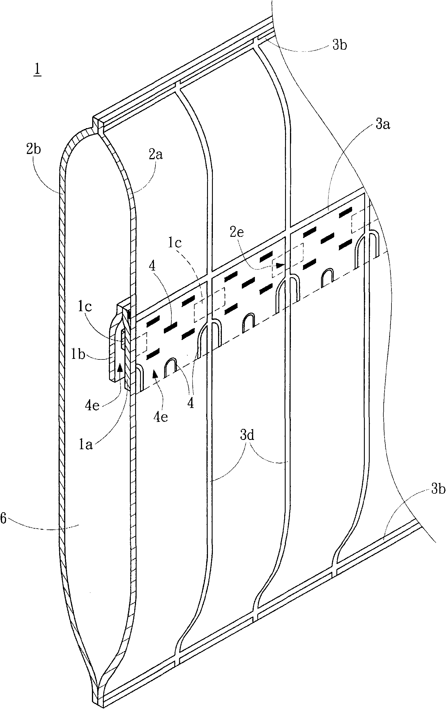
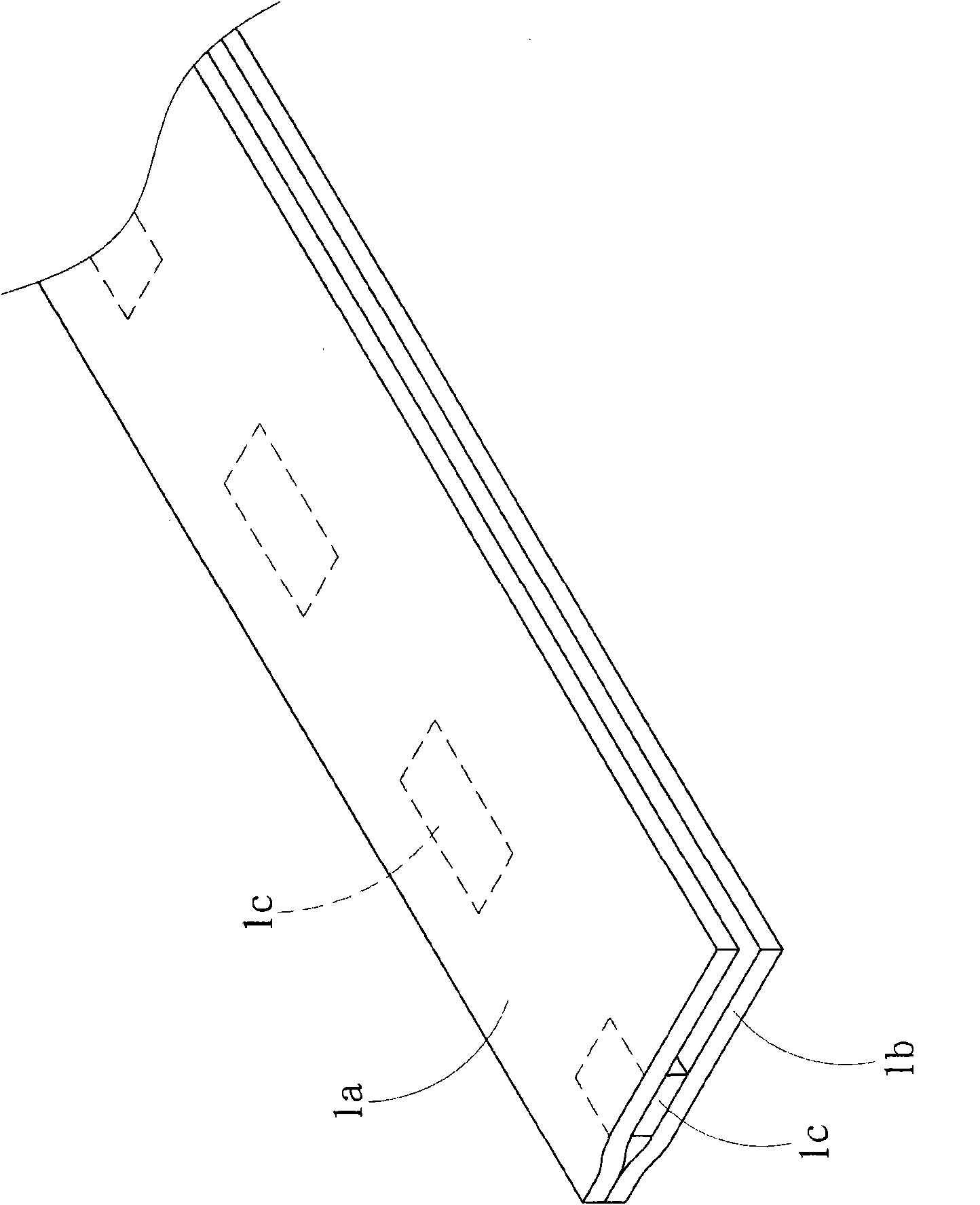
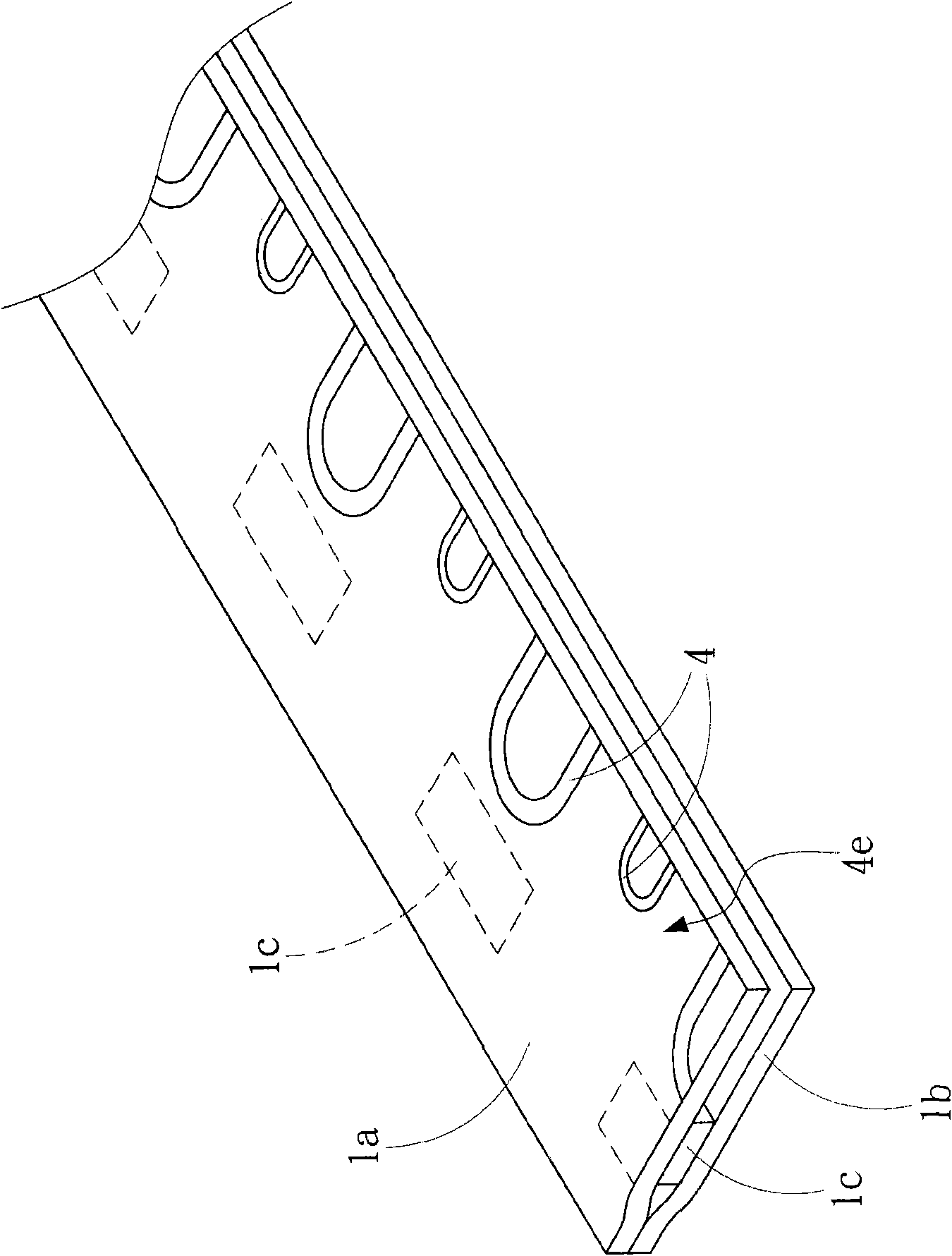
[0040] see figure 1 , Figure 2A , Figure 2B , Figure 2C and Figure 2D , respectively represent the air sealing body with changeable air valve position according to the specific embodiment of the present invention.

[0041] In a specific embodiment of the present invention, the air-tight body 1 with a changeable air valve position includes: a first outer film 2a and a second outer film 2b, two inner films 1a and 1b, a first transverse heat-sealing line 3a, multiple A second transverse heat-sealing line 3b, a plurality of longitudinal heat-sealing lines 3d, a plurality of air columns 6, and a plurality of air inlets 2e.

[0042] Wherein, the first outer membrane 2a is a strip-shaped membrane.

[0043] The two inner membranes 1a and 1b are el...


PUM


Abstract

The invention provides an air seal and a manufacturing method thereof. The air seal comprises a first external membrane, two internal membranes, a first transverse heat sealing line, a second external membrane, longitudinal heat sealing lines, closed gas columns and gas inlets, wherein the two internal membranes are positioned between the two ends of the first external membrane; a heat-resistant material is coated between the two internal membranes; the first transverse heat sealing line is used for adhering the internal membranes to the first external membrane, and is positioned at one end of each of the internal membranes and between the two ends of the first external membrane; the second external membrane is laminated on the first external membrane, so that the internal membranes are positioned between the first external membrane and the second external membrane; the longitudinal heat sealing lines are used for adhering the first external membrane, the second external membrane and the internal membranes; the closed gas columns are positioned between adjacent longitudinal heat sealing lines in the first external membrane and the second external membrane; and the gas inlets are positioned at the position where the longitudinal heat sealing lines are laminated with the heat-resistant material, so that gas is inflated into the gas columns through the gas inlets. In the air seal and the manufacturing method thereof, the position of an air valve structure can be adjusted as required without changing length of the gas columns, and the buffer protection effect of the air seal is effectively maintained.

Description

technical field [0001] The invention relates to the technical field of packaging, in particular to an air-tight body and a manufacturing method thereof. Background technique [0002] The air-sealed body is made of resin film, which is heat-sealed to form an air column in a sealed state, and is equipped with an inflation port for inflation. When the gas is filled into the air column through the inflation port, the air-sealed body can be used for inner packaging as a buffer material. [0003] Existing air seal structures such as U.S. Patent No. 7568508, titled "Continuously inflated air seal and its manufacturing method", use heat sealing means to generate heat seal lines, so as to form multiple air columns by adhering two outer films And the gas-filled channel at one end of the multiple gas columns, and the inner film is provided between the two outer films to form the gas valve structure, so that the gas in the gas-filled channel is filled into multiple gas columns through ...

Claims


Application Information

Patent Timeline
Patent Type & Authority Patents(China)
IPC IPC(8): B65D81/03
Inventor 廖建华廖耀鑫廖国雄
Owner KUNSHAN AIRBAG PACKING CORP
Learn More