Pneumatic stopping structure

A technology of blocking structure and cylinder, applied in the direction of conveyor objects, transportation and packaging, roller table, etc., can solve the problems of large wear of the feeder and wear of the body.

Inactive Publication Date: 2012-03-21
WUXI FORMEN TECHN
View PDF0 Cites 15 Cited by
  • Summary
  • Abstract
  • Description
  • Claims
  • Application Information

AI Technical Summary

Problems solved by technology

[0002] In the process of conveying materials, the existing conveyor often needs to stop the rear materials for a while to ensure the smooth delivery of the front materials. The material is smooth, but the wear on the feeder will be great, because the feeder will directly wear the body during the process of stopping and opening

Method used


Image

  • Pneumatic stopping structure
  • Pneumatic stopping structure
  • Pneumatic stopping structure

Examples


Embodiment Construction

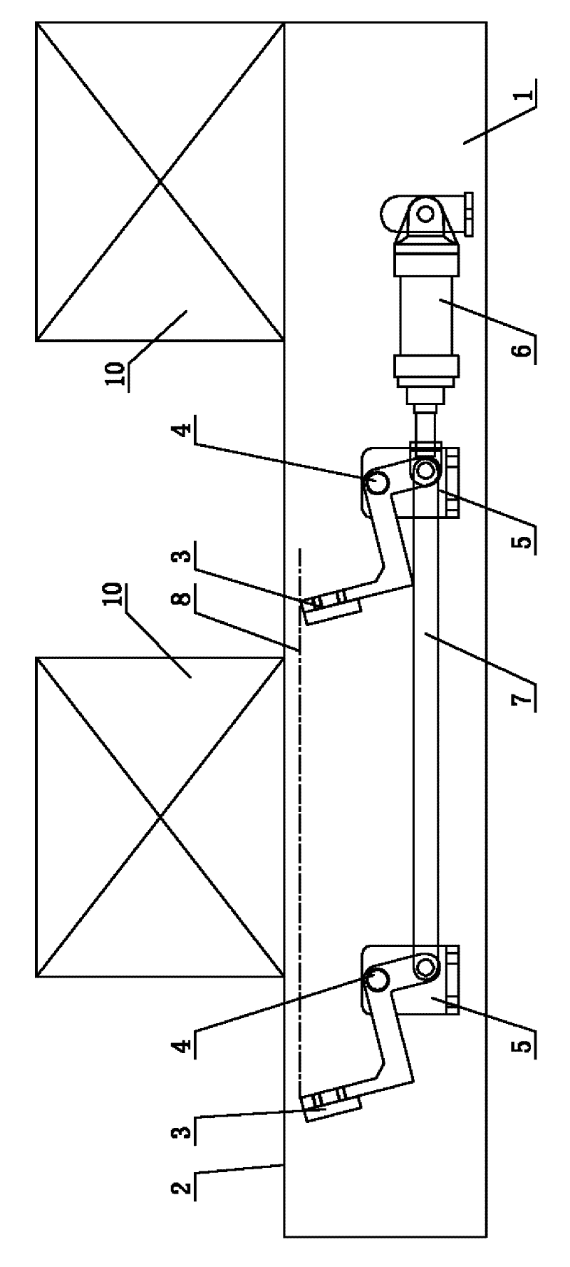
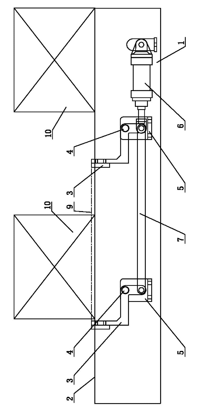
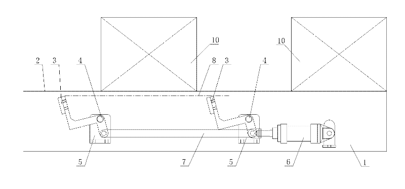
[0010] See figure 1 , figure 2 , which includes a bracket 1, a roller conveyor plane 2, a baffle 3 is arranged in the middle of adjacent rollers (not shown in the figure and belongs to the existing mature structure), the middle part of the baffle 3 is set on one end of the rotary shaft 4, and the rotary shaft The other end of 4 is sleeved in the mounting hole of the base plate 5, the base plate 5 is fastened to the bracket 1, the lower end of the baffle plate 3 is fastened to the piston rod of the cylinder 6, and the cylinder seat of the cylinder 6 is fastened to the bracket 1. The bottoms of two adjacent baffles 3 are connected by a connecting rod 7; figure 1 Among them, 8 is the plane formed by the upper part of the adjacent baffle plate 3 under the normal conveying state; figure 2 Among them, 9 is the plane formed by the upper part of the adjacent baffle plate 3 in the blocking state; figure 1 , figure 2 Among them, 10 is the goods.


PUM


Abstract

The invention provides a pneumatic stopping structure. The pneumatic stopping structure is used for stopping the forward conveying of rear materials on a roller under a running condition of a feeding machine, thereby ensuring the smooth conveying of the front materials and preventing the feeding machine from being abraded. The pneumatic stopping structure comprises a bracket and a roller conveying plane and is characterized in that a baffle is arranged between adjacent roller wheels; one end of a rotating shaft is sleeved in the middle of the baffle; the other end of the rotating shaft is sleeved on a base plate; the base plate is tightly connected to the bracket; a piston rod of a cylinder is tightly connected to the lower end of the baffle; and a cylinder base of the cylinder is tightly connected to the bracket.

Description

technical field [0001] The invention relates to the technical field of conveyor structures, in particular to pneumatic blocking structures. Background technique [0002] In the process of conveying materials, the existing conveyor often needs to stop the rear materials for a while to ensure the smooth delivery of the front materials. The material is smooth, but the wear on the feeder will be great, because the feeder will directly wear the machine body during the process of stopping and opening. Contents of the invention [0003] In view of the above problems, the present invention provides a pneumatic blocking structure, which enables the rear material of the roller table to stop being forwarded when the feeder does not stop, ensuring that the front material is conveyed smoothly without causing wear to the feeder . [0004] The technical scheme of the pneumatic blocking structure is as follows: it includes a bracket and a roller conveying plane, and it is characteri...

Claims


Application Information

Patent Timeline
Patent Type & Authority Applications(China)
IPC IPC(8): B65G13/00B65G47/88
Inventor 李斌
Owner WUXI FORMEN TECHN
Why Eureka
Try Eureka