Combined framework pile
A combined frame and frame side technology, used in sheet pile walls, buildings, infrastructure projects, etc., can solve problems such as affecting the effect of foundation treatment and bearing various loads that are not ideal, and improve resistance to vertical and horizontal loads. Ability, reduction of calculation length, clear and reasonable effect of force transmission
- Summary
- Abstract
- Description
- Claims
- Application Information
AI Technical Summary
Problems solved by technology
Method used
Image
Examples
Embodiment 1
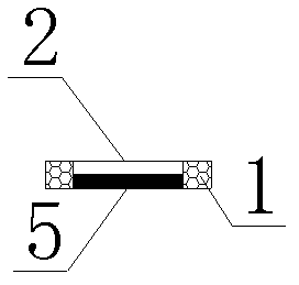
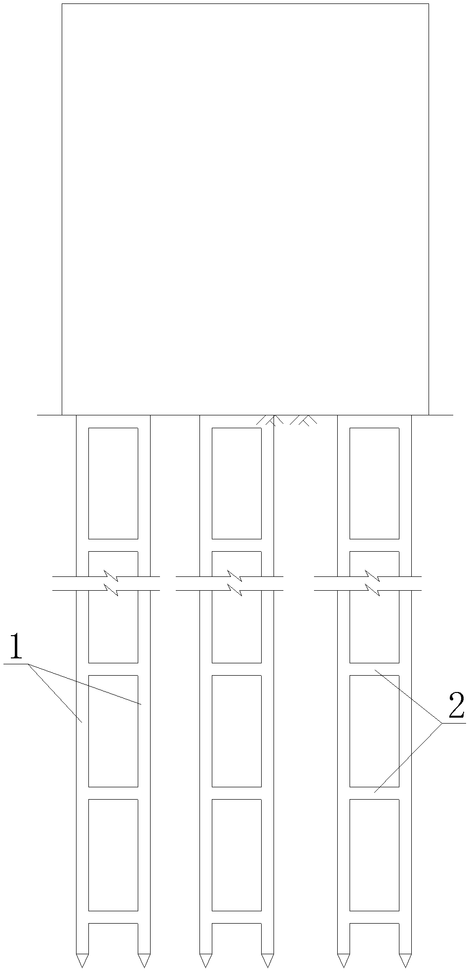
[0044] refer to figure 1 and figure 2 As shown, a combined frame pile of the present invention includes two vertical component piles 1, and the cross-sectional shape of the vertical component piles 1 can be square, triangular, circular or other polygonal shapes, depending on the specific circumstances Be provided with some connectors between two vertical member piles 1, the connector in the present embodiment is the connecting crossbeam 2 that is arranged horizontally, and connecting crossbeam 2 and vertical member pile 1 can adopt the mode of hinged, fixed connection, At the connection node, the concrete is poured after the reserved steel bar is connected according to the rigid node, or the steel structural member is welded according to the requirements of the rigid node to form a rigid node. The material of the vertical member pile 1 and the connecting beam 2 can be steel, reinforced concrete, etc. A common building material; as required, baffles 5 can also be set between ...
Embodiment 2
[0048] refer to Figure 4 and Figure 5 As shown, a combined frame pile of the present utility model has basically the same structure as that of Embodiment 1, the difference being that the connector in this embodiment is a supporting beam 3 that is arranged obliquely, and the supporting beam 3 and the vertical member The pile 1 can be an integral structure, and the connector can also include a support beam 3 and a connecting beam 2 at the same time. In this embodiment, the connecting beam 2 is used at the beginning and end of the vertical member pile 1 . Its method of use is the same as in Example 1.
Embodiment 3
[0050] refer to Figure 6 and Figure 7 As shown, a combined frame pile of the present utility model includes three vertical member piles 1, and several connectors are arranged between each vertical member pile 1. The connectors in this embodiment are collars 4, The connection method between the vertical member pile 1 and the collar 4 can be connected by bolts, and these methods are also applicable to the connection between other connectors and the vertical member pile 1; three vertical member piles 1 are set together by the collar 4 to form a triangle shape; at the same time, the connector can also include the collar 4 and the connecting beam 2 at the same time. In this embodiment, the connecting beam 2 is used on the top of the vertical member pile 1; Each side of the triangle is provided with a baffle plate 5 according to the area separated by the collar 4, and a closed triangular cylindrical structure can be formed between the vertical component piles 1 through the baffle...
PUM
 Abstract
Description
Claims
Application Information
 - R&D
- Intellectual Property
- Life Sciences
- Materials
- Tech Scout
- Unparalleled Data Quality
- Higher Quality Content
- 60% Fewer Hallucinations
Browse by: Latest US Patents, China's latest patents, Technical Efficacy Thesaurus, Application Domain, Technology Topic, Popular Technical Reports.
© 2025 PatSnap. All rights reserved.Legal|Privacy policy|Modern Slavery Act Transparency Statement|Sitemap|About US| Contact US: help@patsnap.com


