Power generation plant with co2 capture and compression

A power generation equipment, CO2 technology, applied in the direction of mechanical equipment, machines/engines, chemical instruments and methods, etc., can solve the problems of power and efficiency loss of generators and motors

Inactive Publication Date: 2015-12-02
GENERAL ELECTRIC TECH GMBH
View PDF7 Cites 0 Cited by
  • Summary
  • Abstract
  • Description
  • Claims
  • Application Information

AI Technical Summary

Problems solved by technology

This increases operational flexibility, but results in additional expense, power and efficiency losses for generators and electric motors

Method used


Image

  • Power generation plant with co2 capture and compression
  • Power generation plant with co2 capture and compression
  • Power generation plant with co2 capture and compression

Examples


Embodiment Construction

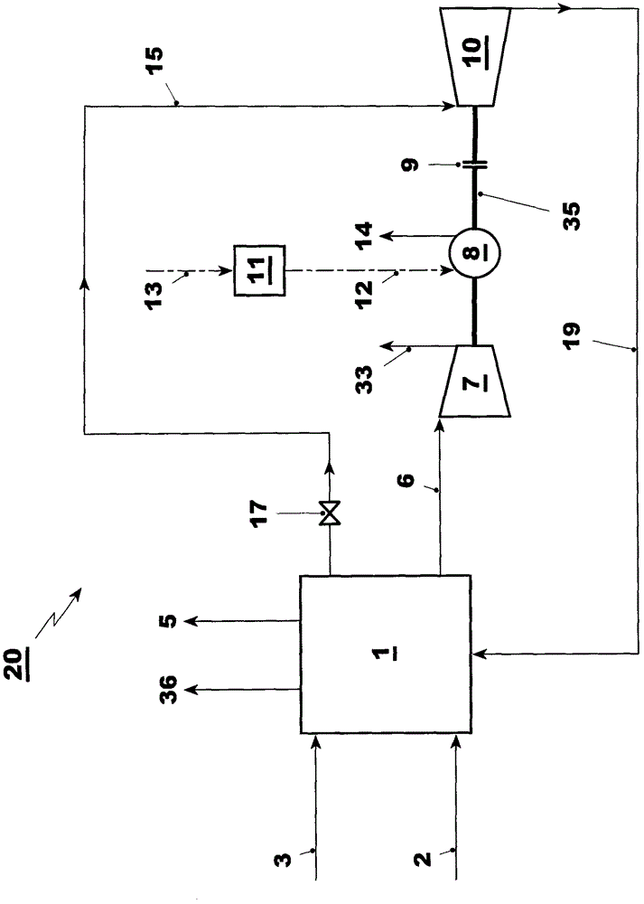
[0076] The power generation plant for carrying out the proposed method comprises a power generation unit 1 comprising CO 2 capture system, CO 2 Compressor 7 , generator 8 , overrunning clutch 9 and steam turbine 10 .

[0077] exist figure 1 A typical arrangement is shown in . The power generation unit 1 is supplied with fuel 2 and ambient air 3 . The power generation unit 1 comprises a conventional fossil fuel fired power plant with at least one water-steam cycle. It may, for example, be a combined cycle power plant, a conventional coal fired steam power plant or an IGCC. The power generation unit includes CO 2 Capture system that removes CO generated during the power generation process 2 . Typically, during backend capture, the CO 2 It is removed from the flue gas, but it can also be removed during the power generation process, as in the case of IGCC.

[0078] In addition to the power delivered to the grid via the mains connection 36, the power generation unit produc...


PUM


Abstract

As CO2 is a main greenhouse gas, CCS (carbon capture and storage) is essential to control global warming. CO2 compression is one of the main steps in the CCS process, which also requires a large amount of energy. For flexible CO2 compressor operation the CO2 compressors are typically powered by electric motors. These increase the operational flexibility but lead to additional expenses, losses in power and efficiency due to generators, transmission and the motors themselves. The main objective of the present invention is to provide a method for the optimized operation of a power plant comprising a power generation unit with a carbon dioxide (CO2) capture system and CO2 compressor with minimum losses during normal operation, and which allows flexible part load operation of the CO2 capture system and compressor. The essence of the invention is a flexible operating method, which allows the use of steam from the power unit to drive a steam turbine, which drives the CO2 compressor via an engaged overrunning clutch if a sufficient amount of steam is available from the power unit, and to drive the CO2 compressor by the generator, which is used as motor when insufficient steam is available from the power unit. At times when no or insufficient steam is available the overrunning clutch is disengaged and the steam turbine may be at standstill or idling.

Description

technical field [0001] The present invention relates to operating with CO 2 A method of capturing and compressing a power generating device and a device for performing such a method. Background technique [0002] CO 2 (Carbon dioxide) is recognized as a major greenhouse gas, and CCS (Carbon Capture and Storage) is considered as one of the possible main means for reducing the release of greenhouse gases to the atmosphere and controlling global warming. In this case, CCS is defined as CO 2 The process of capture, compression, transport and storage. Capture is defined as the process in which CO is removed from the flue gas, either after combustion of a carbon-based fuel 2 , or to remove and dispose of the carbon prior to combustion. For CO removal from flue gas or fuel gas streams 2 Regeneration of any sorbent, sorbent, or other apparatus is considered part of the capture process. [0003] Backend CO 2 Capture or post-combustion capture is a commercially promising techn...

Claims


Application Information

Patent Timeline
Patent Type & Authority Patents(China)
IPC IPC(8): F01K23/10C01B32/50
CPCF01K23/10Y02E20/14Y02E20/16Y02E20/18Y02E20/185Y02E20/32
Inventor J·霍夫曼H·纳格尔李洪涛
Owner GENERAL ELECTRIC TECH GMBH
Why Eureka
Try Eureka