Method for lifting fluid and device

A lifting device, liquid technology, applied in the direction of machine/engine, non-displacement pump, mechanical equipment, etc., to achieve the effect of saving energy consumption

Inactive Publication Date: 2015-02-11
吕夏春
View PDF7 Cites 0 Cited by
  • Summary
  • Abstract
  • Description
  • Claims
  • Application Information

AI Technical Summary

Problems solved by technology

Most of the traditional liquid transportation uses hydraulic pumps, water trucks and other transportation devices that require other power input conversions, which consume energy

Method used


Image

  • Method for lifting fluid and device
  • Method for lifting fluid and device
  • Method for lifting fluid and device

Examples


Embodiment approach 1

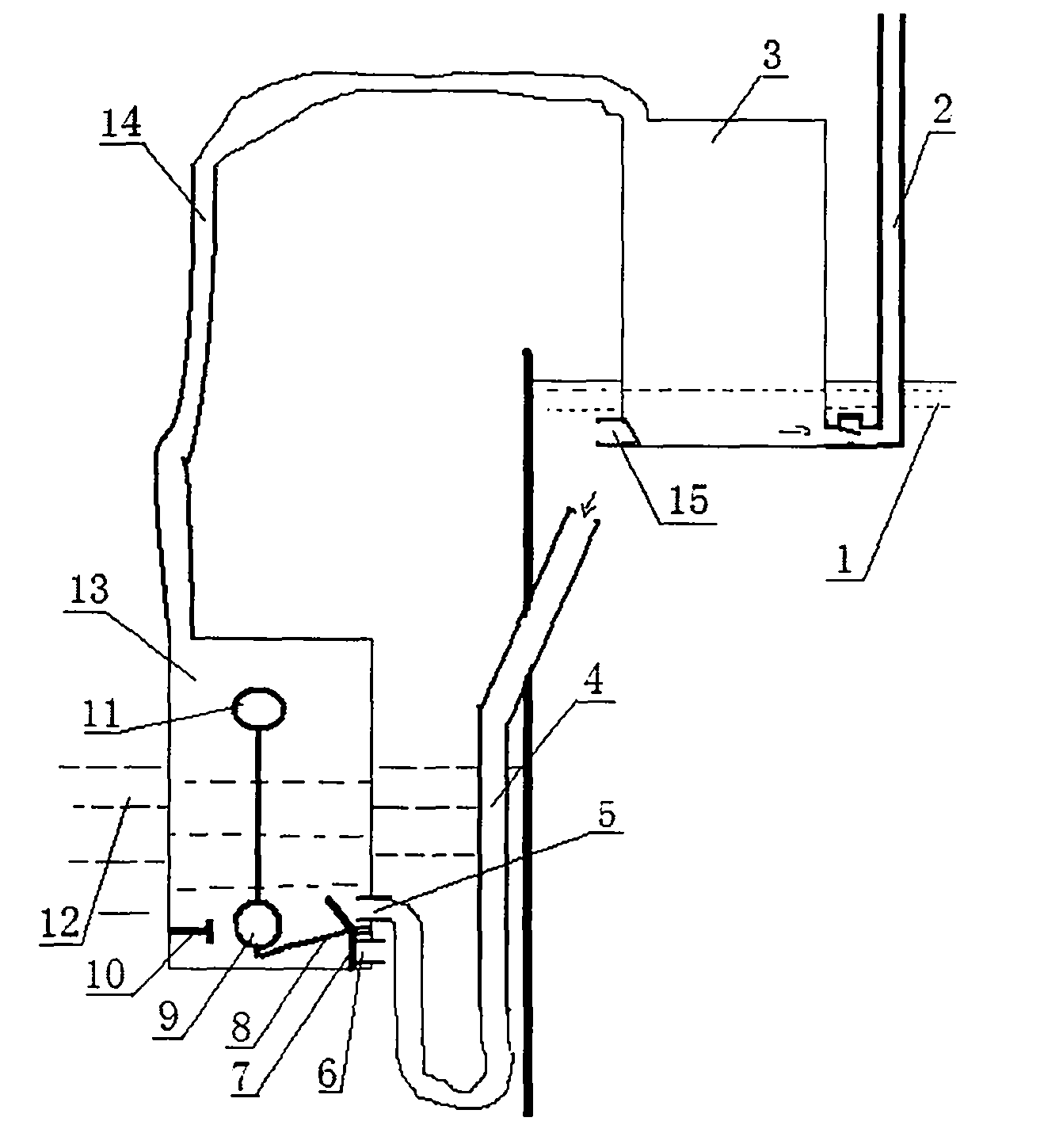
[0019] The implementation is as figure 1 As shown, the liquid lifting device of the present invention includes a liquid pressure feeding mechanism, and the liquid pressure feeding mechanism includes an air pipe 14, an upper container 3, and a lower container 13. The inner cavities of the upper container 3 and the lower container 13 are airtight liquid storage chambers. The top surface of the upper container 3 and the lower container 13 is connected, so that the liquid storage chambers of the upper container and the lower container are communicated. The position of the upper container 3 is higher than that of the lower container 13. The bottom of the upper container 3 is provided with a liquid inlet 15 and a liquid outlet. The bottom of the container 13 is provided with a liquid inlet 5 and a liquid outlet 6, and a one-way valve is installed on the liquid inlet and the liquid outlet of the upper container 3. The liquid outlet of the upper container 3 is connected to the high-le...

Embodiment approach 2

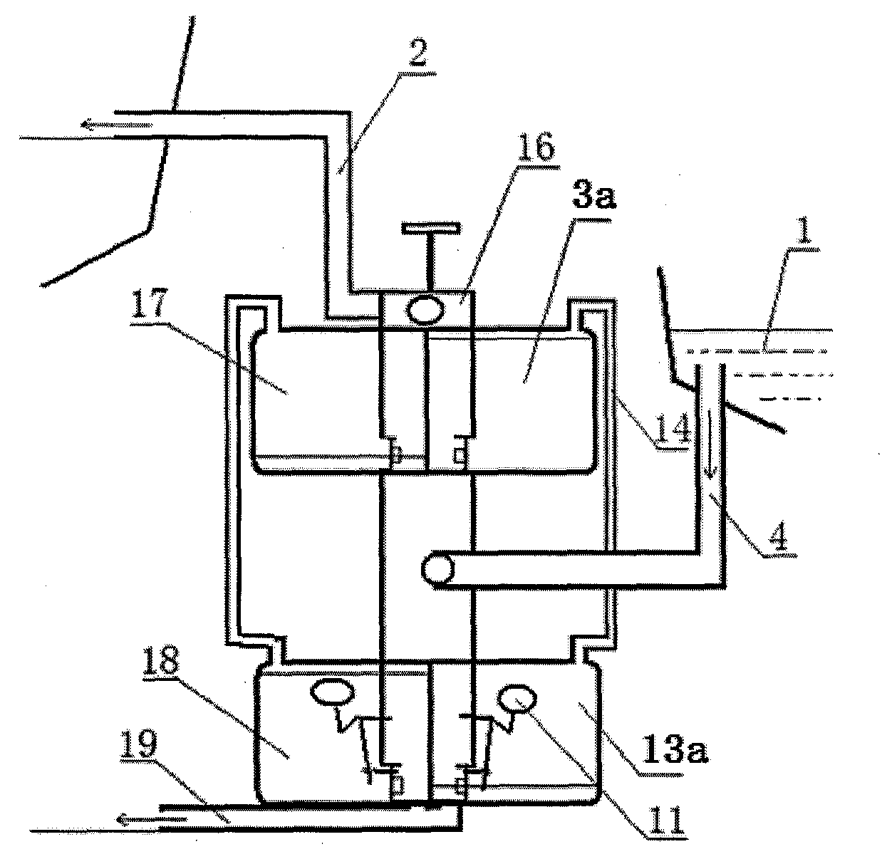
[0021] The second embodiment is as figure 2As shown, the liquid elevating device of the present invention adopts a parallel type, including a bracket 16 and parallel first and second two identical aforementioned liquid pressure feeding mechanisms, the first upper container 3a, the first lower pressure feeding mechanism of the first liquid pressure feeding mechanism The second upper container 17 and the second lower container 18 of the container 13a and the second liquid pressure feeding mechanism are all installed on the support 16, and the liquid outlets of the first upper container 3a and the second upper container 17 are connected with the same high-level output port. The pipe 2 is connected, the liquid outlets of the first lower container 13a and the second lower container 18 are connected with the same low output pipe 19; the first upper container 3a, the second upper container 17, the first lower container 13a, and the second lower container 18 The liquid inlet is conne...

Embodiment approach 3

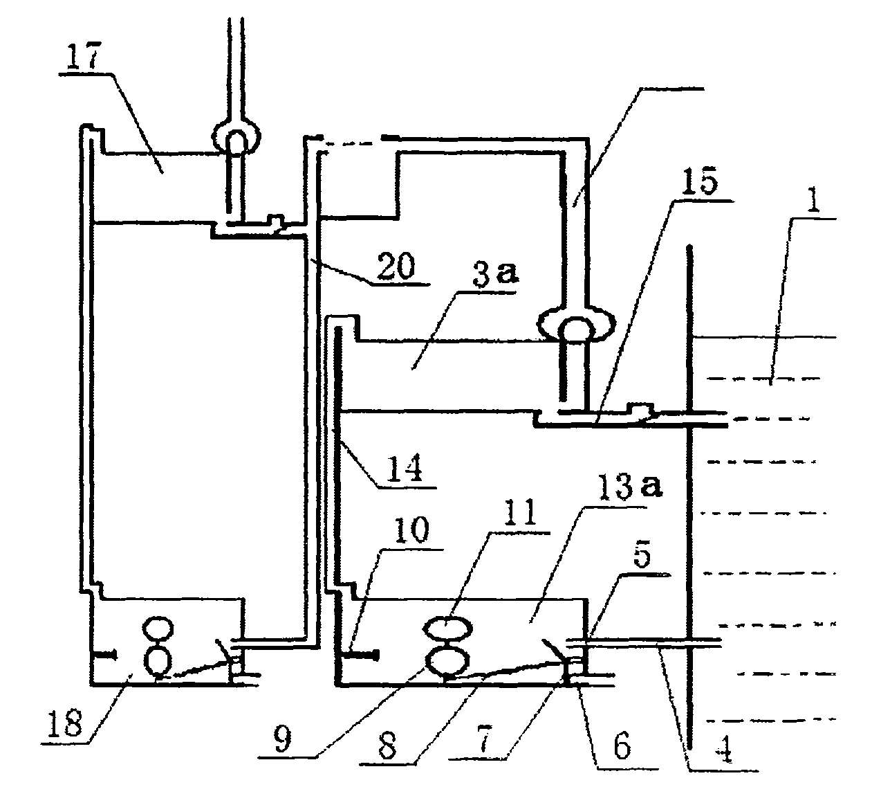
[0022] Three ways to implement image 3 As shown, the liquid lifting device of the present invention adopts a series type, including the first and second two identical aforementioned liquid pressure-feeding mechanisms, the first liquid pressure-feeding mechanism and the second liquid pressure-feeding mechanism are connected in series, which can increase the liquid lifting height, The high-level output pipe 2 of the first liquid pressure-feeding mechanism is connected with the input pipe 20 of the second liquid pressure-feeding mechanism.


PUM


Abstract

The invention discloses a method for lifting fluid and a device, which belong to the technical field of fluid delivery. The conventional fluid delivery method needs conversion of other power input, and the energy is needed to be consumed. According to the invention, an upper fluid reservoir and a lower fluid reservoir which are sealed are used; the top part of the upper fluid reservoir and the top part of the lower fluid reservoir are communicated through an air pipe; and an air column is generated between the upper fluid reservoir and the lower fluid reservoir. The device for lifting the fluid uses inner cavities of an upper container and a lower container as the fluid reservoirs; the fluid reservoirs and the air pipe connected with the top parts form fluid pressure feed mechanisms; the two fluid pressure feed mechanisms are connected in parallel or in series; the fluid inlets and the fluid outlets of the upper container and the lower container are respectively provided with a valve; a fluid input source with the fluid level being higher than the bottom surface of the upper fluid reservoir utilizes source fluid potential energy to force the air column to move between the upper fluid reservoir and the lower fluid reservoir; and when the air column moves to the upper fluid reservoir, according to a principle that intensities of pressure at two ends of the air column are equal, fluid in the upper fluid reservoir is pressed to a high position through a pipeline, so that one part of the source fluid can be lifted and delivered, and the energy consumption is saved.

Description

technical field [0001] The invention belongs to the technical field of liquid transportation, and in particular relates to a liquid lifting method and device for lifting the liquid to a high place by utilizing the potential energy conduction conversion of the liquid itself. Background technique [0002] The phenomenon of transporting liquid to high places exists in various fields such as agricultural irrigation, aquaculture, water conservancy and hydropower, production and life. Most of the traditional liquid transportation uses hydraulic pumps, water trucks and other transportation devices that require other power input conversions, which consume energy. Contents of the invention [0003] The object of the present invention is to provide a liquid lifting method, device and method of using the device, which can realize liquid lifting and transportation by only using the potential energy transmission and transformation of the liquid itself without other power input. [...

Claims


Application Information

Patent Timeline
Patent Type & Authority Patents(China)
IPC IPC(8): F04F1/00
Inventor 吕夏春
Owner 吕夏春
Why Eureka
Try Eureka