A pneumatic lifting device

A lifting device and protection device technology, applied in the field of pneumatic lifting, can solve the problems of insufficient lifting force and easy oil leakage of hydraulic drive, and achieve the effects of ensuring safety, realizing flexible transmission, and strong radial load capacity.

Active Publication Date: 2017-06-20
BEIJING INST OF SPECIALIZED MACHINERY
View PDF6 Cites 0 Cited by
  • Summary
  • Abstract
  • Description
  • Claims
  • Application Information

AI Technical Summary

Problems solved by technology

[0003] The purpose of the present invention is to provide a pneumatic lifting device to solve the problem that the lifting force is not large enough and the hydraulic drive is easy to leak oil

Method used


Image

  • A pneumatic lifting device
  • A pneumatic lifting device
  • A pneumatic lifting device

Examples


Embodiment Construction

[0011] In order to make the purpose, content, and advantages of the present invention clearer, the specific implementation manners of the present invention will be further described in detail below in conjunction with the accompanying drawings and embodiments.

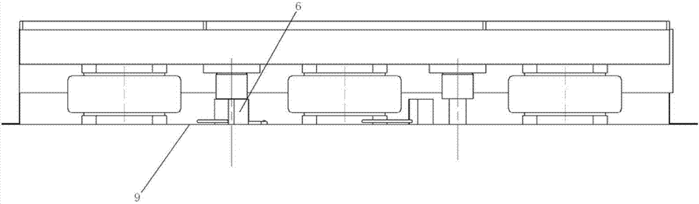
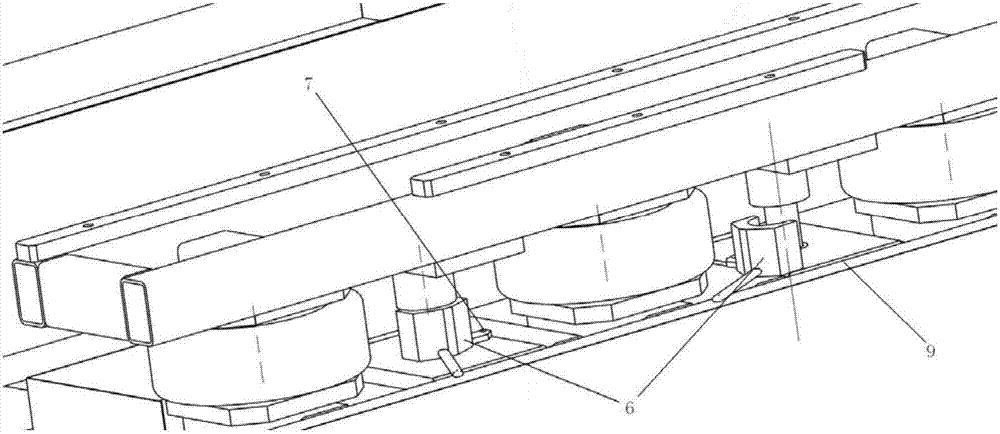
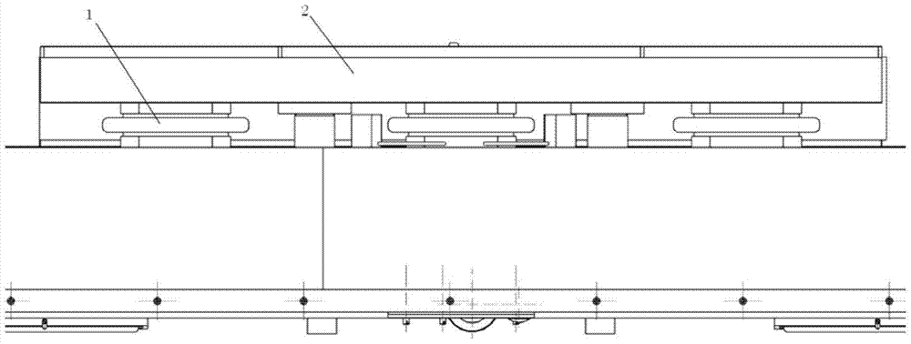
[0012] Such as Figure 1-2 As shown, a pneumatic lifting device of the present invention includes a lifting platform 2, three airbag cylinders 1, a guide rod 3, a wear-resistant copper sleeve 4, a copper sleeve fixing seat 5, a lifting protection device 6, a pin Shaft 7, guide rod limit block 8 and fixed frame 9;

[0013] The lifting platform 2 is the main force-bearing part, which is in direct contact with the load. The upper surface of the airbag cylinder 1 is fixedly connected to the lower surface of the lifting platform 2, and the lower surface is fixedly connected to the upper part of the fixed frame 9; the wear-resistant copper sleeve 4 is fixed on the upper part of the fixed frame 9 through the copper sleeve fi...


PUM


Abstract

The invention discloses a pneumatic lifting device, comprising a lifting platform, an airbag-type cylinder, a guide rod, a wear-resistant copper sleeve, a lifting protection device, a pin shaft, a guide rod limit block and a fixing frame; the upper surface of the lifting platform In direct contact with the heavy load, the upper surface of the airbag type cylinder is fixedly connected with the lower bottom surface of the lifting platform, and the lower surface of the airbag type cylinder is fixedly connected with the upper part of the fixing frame; the wear-resistant copper sleeve is fixed on the upper part of the fixing frame, and the top of the guide rod is pierced. After passing through the wear-resistant copper sleeve, it is fixedly connected to the fixed sleeve on the lower bottom surface of the lifting platform, and the guide rod limit block is fixed at the bottom of the guide rod; when the main air circuit supplies air to the air bag type cylinder 1, the air bag type cylinder inflates and expands, thereby promoting the lifting The lifting platform and the guide rod move upward along the inner side of the wear-resistant copper sleeve 4 . The invention adopts the airbag type cylinder, which has strong axial and radial load bearing capacity, can realize flexible transmission of bearing capacity, effective adjustment of stroke and efficient control of vibration, and ensures the safety of the whole lifting and transportation process.

Description

technical field [0001] The invention belongs to the technical field of pneumatic lifting, and in particular relates to a pneumatic lifting device for safe lifting and transportation. Background technique [0002] Generally, the commonly used methods of lifting are: lifting by hydraulically driven scissor mechanism, direct lifting by electric cylinder, etc. In the case of a large lifting force, hydraulically driven scissors are generally used to lift, but this method requires hydraulic pumps and other components, which is prone to oil leakage and unclean work sites; and direct lifting by electric cylinders not only costs more High, and the lift is not strong enough. Contents of the invention [0003] The purpose of the present invention is to provide a pneumatic lifting device to solve the problems of insufficient lifting force and oil leakage due to hydraulic drive. [0004] The technical solution of the present invention is: a pneumatic lifting device, including a lifti...

Claims


Application Information

Patent Timeline
Patent Type & Authority Patents(China)
IPC IPC(8): B66F7/16
Inventor 马伟王韡褚昌军
Owner BEIJING INST OF SPECIALIZED MACHINERY
Why Eureka
Try Eureka