Bottom lifting frame and hydraulic support

A technology of hydraulic support and bottom frame, which is applied to mine roof support, mining equipment, earthwork drilling, etc., can solve problems such as affecting the operation of hydraulic support and falling off of pins, and achieves the effect of simple structure, avoiding failure and saving cost.

Pending Publication Date: 2020-07-24
SANY HEAVY EQUIP
View PDF0 Cites 0 Cited by
  • Summary
  • Abstract
  • Description
  • Claims
  • Application Information

AI Technical Summary

Problems solved by technology

When the force is damaged, the welding seam will be opened and the pin

Method used


Image

  • Bottom lifting frame and hydraulic support
  • Bottom lifting frame and hydraulic support
  • Bottom lifting frame and hydraulic support

Examples


Embodiment 1

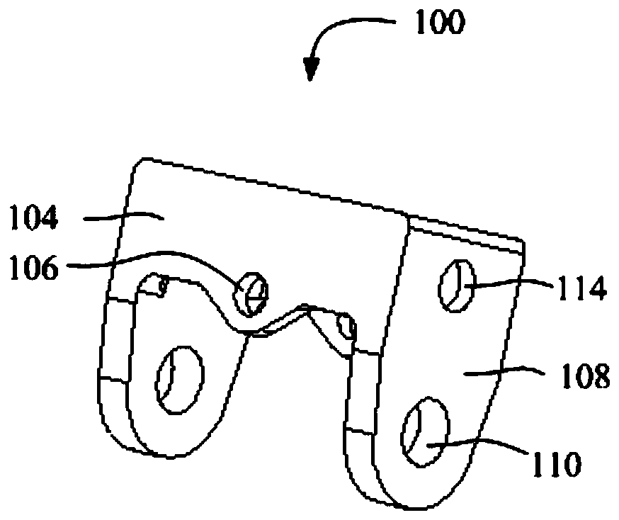
[0044] like Figure 1 to Figure 5 As shown, a bottom lift frame 100 proposed by the first embodiment of the present invention includes: a top plate 102 , a side plate 104 and an ear plate 108 .

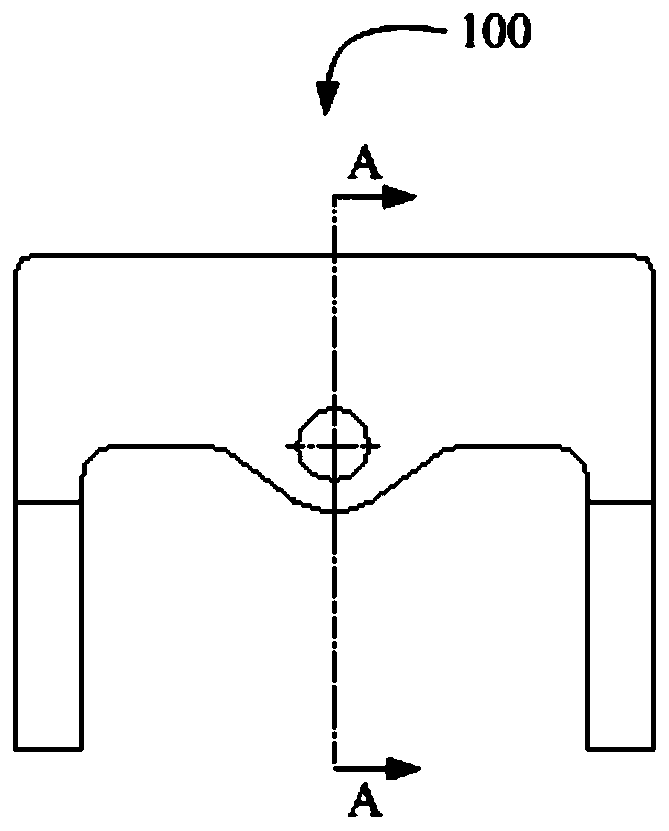
[0045] The lower surface of the top plate 102 is provided with a first arc structure 112; the side plate 104 is connected to the top plate 102 and is located on both sides of the top plate 102, and the side plate 104 is provided with a first pin hole 106; the ear plate 108 is connected to the top plate 102, located in On both sides of the top plate 102 , the ear plate 108 and the side plate 104 are arranged around the periphery of the top plate 102 , and the ear plate 108 is provided with a second pin hole 110 ; wherein, the bottom lifting frame 100 is configured as an integral structure.

[0046] The bottom-lifting frame 100 provided in this embodiment, by setting the top plate 102, the side plate 104 and the ear plate 108 as an integrated structure, avoids failures caused by the wel...

Embodiment 2

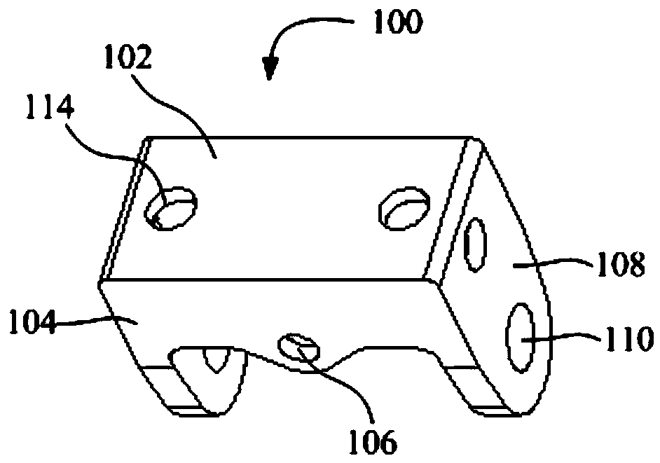
[0049] like figure 1 As shown, in the above embodiment, further, the bottom lifting frame 100 further includes a hoisting hole 114 . The hoisting hole 114 is provided on the ear plate 108 .

[0050] In this embodiment, the hoisting holes 114 are provided on the lugs 108, and are directly hoisted and used when installing the bottom-lifting frame 100, thereby reducing the use of materials such as hoisting ring seats and hoisting rings, and reducing costs.

[0051] Further, as figure 2 As shown, the hoisting holes 114 are also provided on the top plate 102 .

[0052] In this embodiment, the hoisting holes 114 are provided on the side panel 104 and the top panel 102 at the same time, which facilitates manual operation and also reduces the weight of the bottom lifting frame 100 .

Embodiment 3

[0054] like Image 6 As shown, a hydraulic support provided by a third embodiment of the present invention includes a bottom-lifting mechanism 200 and a bottom-lifting frame 100 as in any of the above-mentioned embodiments.

[0055] The bottom lifting mechanism 200 includes a bottom lifting jack 202 hinged to the bottom lifting frame 100 , the bottom lifting frame 100 is located above the bottom lifting mechanism 200 , and the bottom lifting frame 100 is hinged to the bottom lifting mechanism 200 .

[0056] In this embodiment, since the hydraulic support includes the bottom lifting frame 100 in any of the above embodiments, the hydraulic support has all the beneficial effects of the bottom lifting jack 202 in any of the above embodiments, and further improves the service life of the hydraulic support . The bottom lifting jack 202 is hinged with the bottom lifting frame 100 . The bottom lifting frame 100 is located above the bottom lifting mechanism 200 and is hingedly connec...


PUM


Abstract

The invention provides a bottom lifting frame and a hydraulic support. The bottom lifting frame comprises a top plate, side plates and lug plates, the lower surface of the top plate is provided with afirst arc structure, the side plates are connected with the top plate and located on the two sides of the top plate, first pin holes are formed in the side plates, the lug plates are connected with the top plate and located on the two sides of the top plate, the lug plates and the side plates are arranged on the peripheral side of the top plate in a surrounding mode, and second pin holes are formed in the lug plates; and the bottom lifting frame is configured to be of an integrated structure. According to the bottom lifting frame, the top plate, the side plates and the lug plates are arrangedto be of the integrated structure, faults caused by open welding of a welding seam of a welding structure are avoided, the structure is simple, and cost is saved. The first arc structure on the lowersurface of the top plate is in arc contact with the top of a bottom lifting jack, and damage caused by bending deformation of a connected pin shaft is avoided.

Description

technical field [0001] The invention relates to the technical field of coal mine equipment, in particular to a bottom lifting frame and a hydraulic support. Background technique [0002] In the process of lifting the bottom of the hydraulic support, the bottom of the cylinder of the lifting jack extends out and contacts the top surface of the push rod, and then continues to pressurize, the lifting jack will continue to extend its stroke, and the front end of the base tilts upward. When the hydraulic support moves forward, operate the push jack, retract its piston rod, and the support moves forward. During the whole process, the cylinder bottom of the bottom-lifting jack is always in frictional contact with the top surface of the push rod. The underground environment is fickle, and the impact forces of different sizes may easily cause the welding seam of the lugs on the base and the lifting bottom frame to open. [0003] The lifting bottom frame is welded by steel plates, an...

Claims


Application Information

Patent Timeline
IPC IPC(8): E21D23/08
CPCE21D23/08
Inventor 朱庆波段存虎孙晓亮
Owner SANY HEAVY EQUIP
Why Eureka
Try Eureka