
Concentrate sampling machine

A sampling machine, concentrate technology, applied in sampling devices and other directions, can solve problems such as high labor intensity

Inactive Publication Date: 2012-03-21
LIYANG CITY ZHENGXIANG PRECISION MACHINERY
View PDF0 Cites 0 Cited by
  • Summary
  • Abstract
  • Description
  • Claims
  • Application Information

AI Technical Summary

Problems solved by technology

[0003] The invention provides a concentrate sampling machine driven by a belt for transporting concentrate to solve the problem of high labor intensity of manual sampling

Method used


Image

  • Concentrate sampling machine
  • Concentrate sampling machine
  • Concentrate sampling machine

Examples


Embodiment Construction

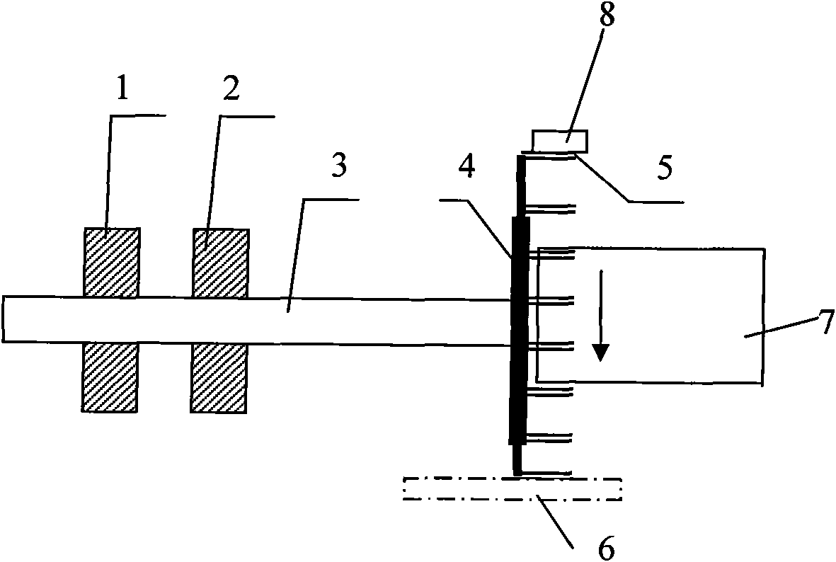
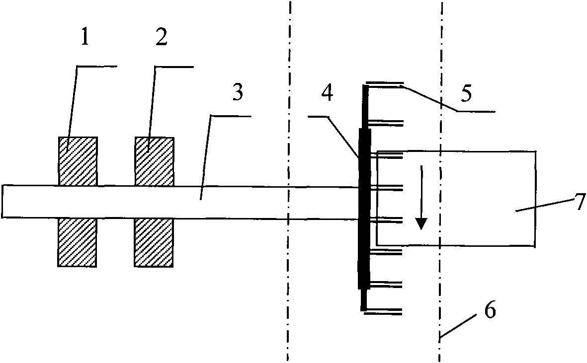
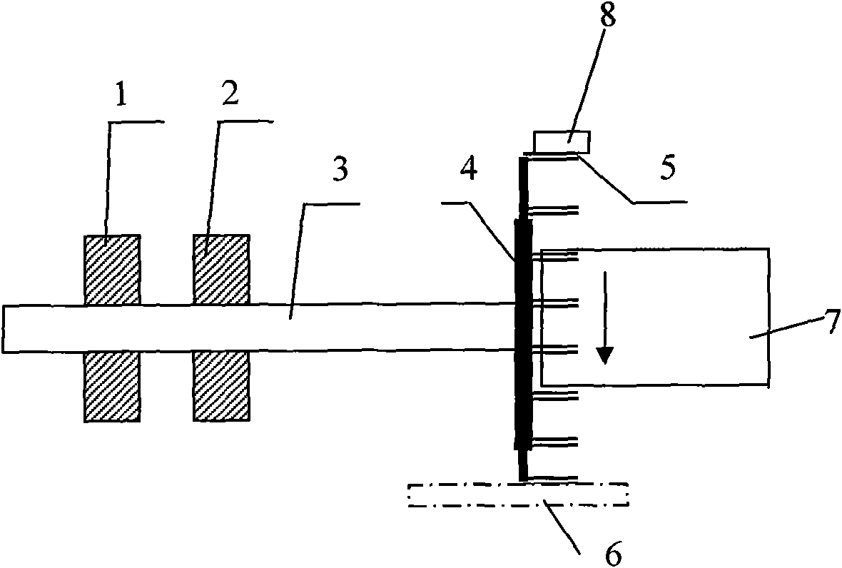
[0010] In the figure, in the concentrate sampling machine, multiple sampling spoon heads 5 are evenly distributed on the circumference of the turntable 4, the turntable 4 is connected with a coaxial rotating shaft 3, and the rotating shaft 3 is connected to a bracket (not shown) through two bearing seats 1, 2 )on. The sampling spoon head 5 is a round rod parallel to the rotating shaft, and the round rod is perpendicular to the movement direction of the belt 6. The belt 6 is located below and cuts the circumference of the sampling spoon head 5; the scraper 8 is located above and tangent to the circumference of the sampling spoon head, and a receiving hopper 7 is arranged below the scraper 8.

[0011] Because the sampling spoon head presses the belt, when the belt moves forward, the friction force and the impulse generated by the moving concentrate push the sampling spoon head to continuously rotate around the axis of the rotating shaft. During the rotation of the sampling spoon h...


PUM


Abstract

The invention provides a concentrate sampling machine driven by a belt delivering concentrate to resolve the problem that manual sampling is large in labor intensity. A plurality of sampling spoon heads of the sampling machine are positioned on the circumference of a rotary plate which is connected with a coaxial rotary shaft located on a support, the circumference where the sampling spoon heads are positioned is secant with the surface of the belt delivering the concentrate, a scraping blade is tangent with the circumference where the sampling spoon heads are positioned, and a material receiving hopper is arranged under the scraping blade.

Description

Technical field [0001] The invention relates to a concentrate sampling machine for sampling dehydrated concentrates of various mines, in particular to a sampling machine with a moisture content of 5%-20%. Background technique [0002] In the production process of various mines, it is necessary to dehydrate and filter the beneficiation products to facilitate storage and transportation. The filtered concentrate belongs to the process-type material in the product classification and has the characteristics of continuity; in order to achieve a higher representativeness of concentrate sampling, this requires that the sampling of the concentrate must be continuous; while manual sampling and The robotic sampling often used in China simply cannot meet this requirement. When collecting samples, it is easy to have unequal sampling interval and uneven sampling amount, which results in poor representativeness of samples and high labor intensity of operators. Summary of the invention [0003]...

Claims


Application Information

Patent Timeline
IPC IPC(8): G01N1/12
Inventor 李锁峰
Owner LIYANG CITY ZHENGXIANG PRECISION MACHINERY
Learn More