Drill cutting sampler

a sampler and drill cutting technology, applied in the field of drill cutting samplers, can solve the problems of loss of drill cutting record, inability to acquire wireline logs, poor quality,

Inactive Publication Date: 2014-05-27
RIEBERER WILLY
View PDF25 Cites 1 Cited by
  • Summary
  • Abstract
  • Description
  • Claims
  • Application Information

AI Technical Summary

Benefits of technology

[0015]The planar member is covered by adjustable plates so that only a pre-selected ratio of the cuttings on the vibratory screen are entrained onto the perforated portion of the planar member. The drill cuttings for any particular drill-hole cross-section may thus be uniformly sampled and the resulting sample of a selectively pre-determined volume for ease of and efficient removal for analysis.

Problems solved by technology

The importance of such samples are increased when, after drilling is complete, a wireline log cannot be acquired or is of poor quality because of a damaged bore.
First, the container in which the samples accumulated would often fill to the top and overflow.
Drill cuttings falling from the shale shaker when the container was full were not sampled and the record for such drill cuttings lost.
Loss of drill cutting samples may also occur when fluids are accidentally introduced into the container collecting the samples.
Such may occur as a result of a blinded shaker screen; that is, the screen becomes clogged and permits circulation fluid to flow with the drill cuttings into the container.
Samples may also be lost as a result of water from a hose, which is used to clean the shale shaker, entering the container.
In addition, heavy rain and, in offshore drilling operations, waves may introduce water into the container, thus greatly reducing or destroying the information obtainable from the samples.

Method used


Image

  • Drill cutting sampler
  • Drill cutting sampler
  • Drill cutting sampler

Examples


Embodiment Construction

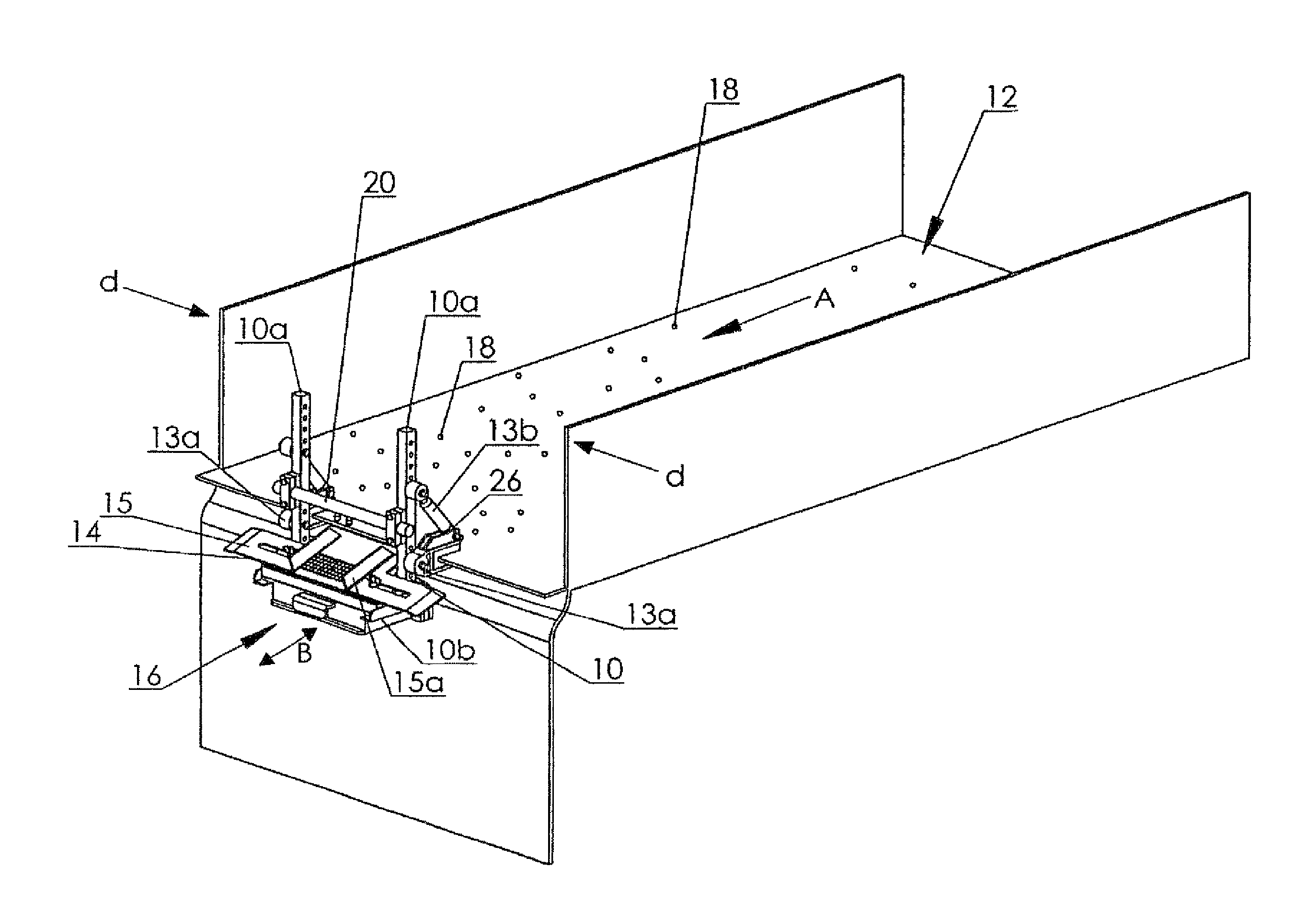
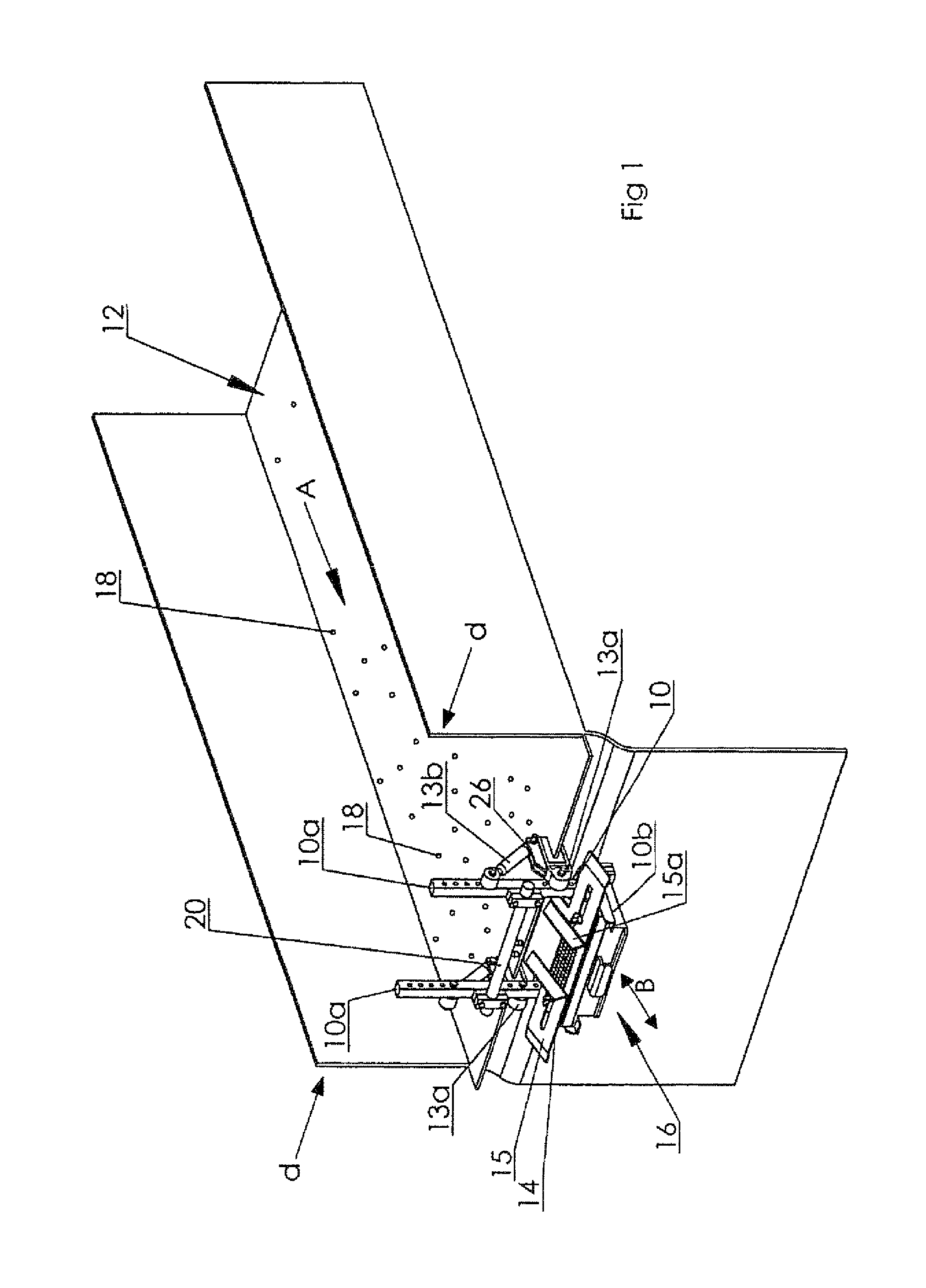
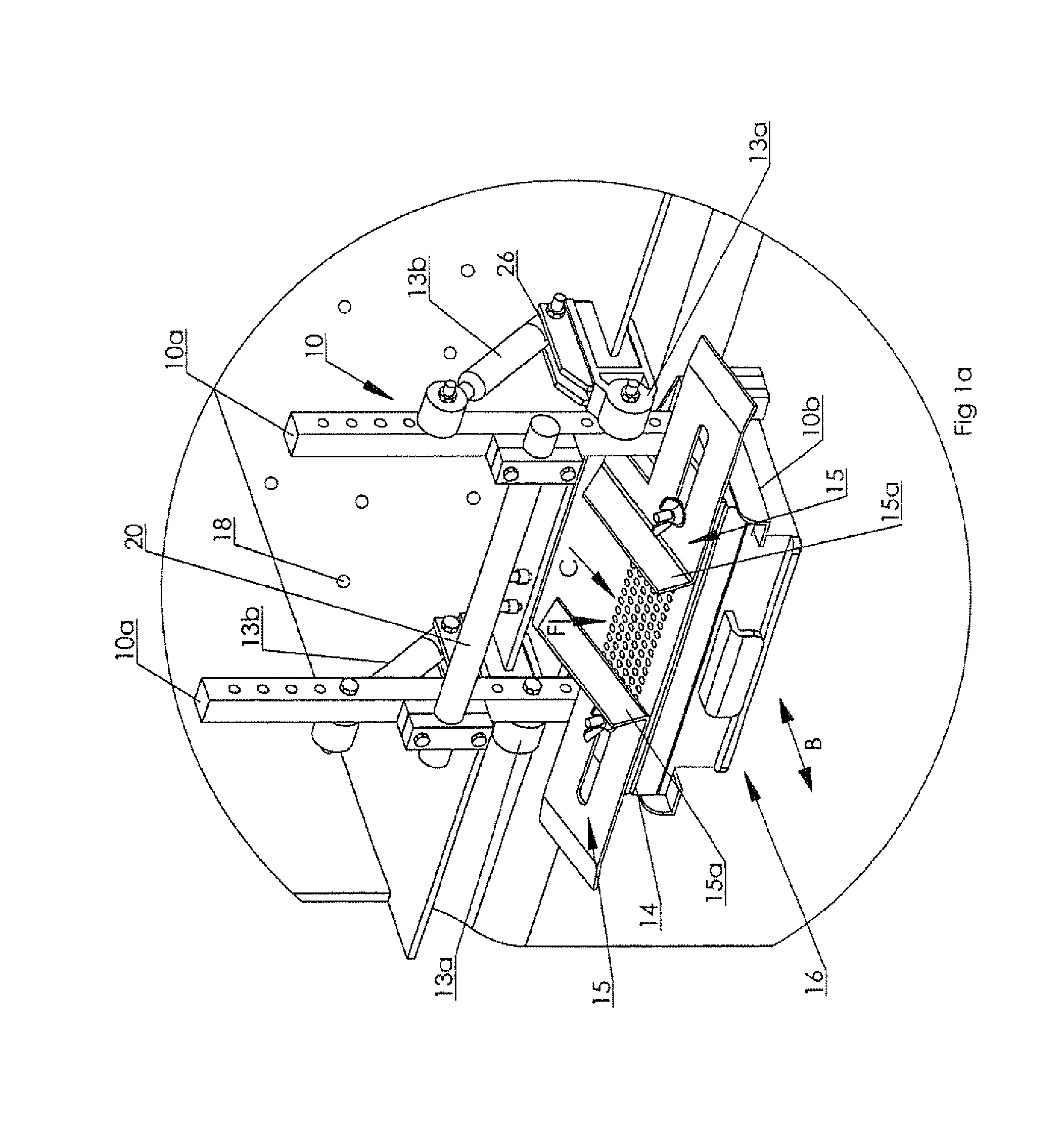
[0025]As may be seen in the accompanying figures wherein like characters of reference denote corresponding parts in each view, the drill cutting sampler according to one embodiment of the present invention includes a supporting frame 10 adapted to be mounted in cooperation with the downstream end of a shale shaker 12 for supporting a perforated plate or sieve screen (also collectively herein referred to as perforated plate 14) in the outflow path of drill cuttings exiting the shale shaker. The perforated plate 14 cooperates with a removable cutting collector 16 removably mounted beneath perforated plate 14 for collecting a sampling of cuttings passing over perforated plate 14 wherein a percentage of the cuttings 18 are washed by spray water from a sprayer 20 through perforations 14a of perforated plate 14. Perforated plate 14 allows cuttings of a desired size to pass through into the collector 16 while all undesired larger cuttings are rejected and pass over the plate, being both wa...


PUM

PropertyMeasurementUnit
widthaaaaaaaaaa
mesh sizeaaaaaaaaaa
mesh sizeaaaaaaaaaa

Abstract

A device for sampling drill cuttings includes a frame, an inclinedhaving a perforated planar member mounted on the frame, a sprayer for washing cuttings down over the perforations, and a. A removable open-topped cuttings collector mounted under the perforated planar member, the. The perforated member cooperatingcooperates with the downstream end of a vibratory screen over which the cuttings pass before translating onto the perforated screen. The frame mounts to the vibratory screen so that vibrations of the vibratory screen also vibrate the perforated planar member and cuttings collector.

Description

CROSS REFERENCE TO RELATED APPLICATION[0001]This application is a Continuation-in-Part of U.S. patent application Ser. No. 11 / 407,078 filed Apr. 20, 2006 now U.S. Pat. No. 7,363,829.FIELD OF THE INVENTION[0002]This invention relates to methods and apparatus for taking samples from the cuttings contained in effluent including circulation fluid from a drill hole used for exploratory drilling and in particular to a sampling device mountable in cooperation with a vibratory separator used conventionally in the art for separating drill cuttings from fluid so that the fluid may be recycled for reuse.BACKGROUND OF THE INVENTION[0003]As stated by Barrett in his U.S. Pat. No. 4,718,289 which issued Jan. 12, 1988 for a Drill Cuttings Sample Collector, exploratory wells are drilled to evaluate penetrated rock formations for producible hydrocarbons. In drilling such wells (and in drilling production wells), circulation fluid is pumped down a string of drill pipe and through a drill bit at the lo...

Claims


Application Information

Patent Timeline
Patent Type & Authority Patents(United States)
IPC IPC(8): G01N1/04
CPCE21B49/005E21B49/02E21B21/065G01N1/2035G01N15/0272G01N33/24G01N2001/1025G01N2001/2007
Inventor RIEBERER, WILLY
Owner RIEBERER WILLY
Why Eureka
Try Eureka