Method and system for realizing standby route based on active detection technique
A technology of active detection and detection method, applied in the direction of transmission system, digital transmission system, electrical components, etc., can solve the problem of limitation of fault detection means, inability to realize fault detection and recovery, and bonus
- Summary
- Abstract
- Description
- Claims
- Application Information
AI Technical Summary
Problems solved by technology
Method used
Image
Examples
Embodiment 1
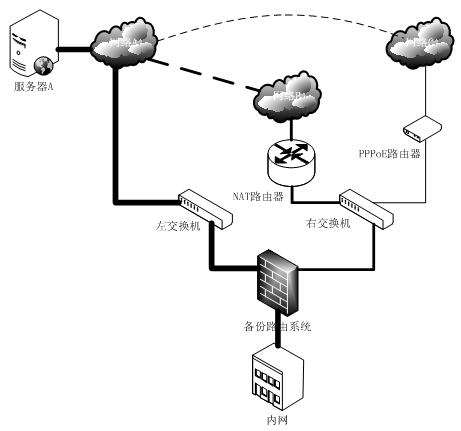
[0030] figure 1 A typical network topology of a backup routing system based on active detection technology is shown. The routing backup system is connected to the outside world through three Ethernet network interfaces (network ports). The lower network port is connected to the internal network. The left network port is directly connected to network A through the next hop route of the left switch. A switch connects two networks at the same time. The left side is connected to network B through a NAT router, and the right side is connected to network C through a PPPoE router.
[0031] The request to access network A from the intranet can have three different paths:
[0032] (1) Access directly through network A through the left switch;
[0033] (2) Access through the right switch, through the NAT router, network B, and network A
[0034] (3) Access through the right switch, PPPoE router, network C, and network A
[0035] Among them, the first path is fast and the cost is lo...
Embodiment 2
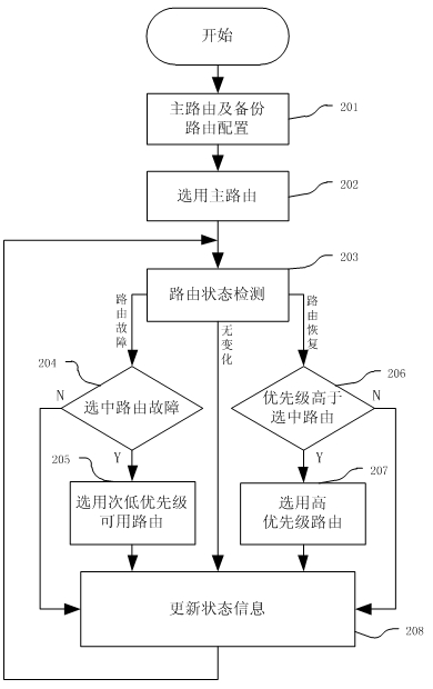
[0037] figure 2 The workflow of implementing the backup routing method based on active detection technology is shown.
[0038] As shown in step 201, in the initial state, the administrator configures the main route and the backup route according to his own network topology requirements, and configures the corresponding route detection method and detection time interval according to the type and importance of each route;
[0039] As shown in step 202, when the configuration has just been completed, due to the lack of health status information of each route, the main route is directly selected earlier;
[0040] As shown in step 203, each detection method of each route is detected separately according to the administrator's configuration. For the detection that adopts the blocking monitoring method, it can be implemented in a centralized manner and processed separately; for the detection that requires polling, it needs to be checked separately according to the specified time in...
Embodiment 3
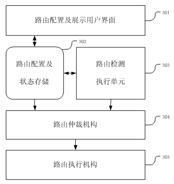
[0047] image 3 A system module architecture for implementing the present invention is shown, the system module architecture includes a routing configuration and display user interface module 301, a routing configuration and status storage module 302, a routing detection module 303, a routing arbitration mechanism module 304 and a routing execution mechanism module 305 .
[0048] Module 301 is used to configure the main and backup routes, including specific routing configuration information, routing priority weights, etc., and modify the selected routing detection method, detection time interval and specific configuration information related to detection; through this The module can also display the current system status, including the configuration information of the main route and the backup route, the selection of the current route, the health status of each route, and the specific details of various detections of each route, such as the current Detection activity, last de...
PUM
 Abstract
Description
Claims
Application Information
 - R&D
- Intellectual Property
- Life Sciences
- Materials
- Tech Scout
- Unparalleled Data Quality
- Higher Quality Content
- 60% Fewer Hallucinations
Browse by: Latest US Patents, China's latest patents, Technical Efficacy Thesaurus, Application Domain, Technology Topic, Popular Technical Reports.
© 2025 PatSnap. All rights reserved.Legal|Privacy policy|Modern Slavery Act Transparency Statement|Sitemap|About US| Contact US: help@patsnap.com


