
Homotaxial paddle mixer

A technology of mixers and paddles, which is applied to mixers, mixing methods, mixers with rotating stirring devices, etc., can solve the problems of general crushing effect, easy adhesion, and increased material residue in mixers, etc.

Inactive Publication Date: 2012-03-28
JIANGSU MUYANG GRP CO LTD
View PDF6 Cites 6 Cited by
  • Summary
  • Abstract
  • Description
  • Claims
  • Application Information

AI Technical Summary

Problems solved by technology

Its shortcoming is that the crushing device can only crush part of the agglomerated materials thrown up by the blades, so the crushing process is intermittent, and after the materials are thrown up, only part of the materials passing through the crushing device are crushed, and the crushing process It is discontinuous, therefore, the overall crushing effect of the existing technology on the oil mass produced in the mixed material is general
In addition, when the materials and oil lumps thrown up by the blades are broken by the crushing device, they splash around and easily adhere to the upper part of the mixing chamber, resulting in an increase in the residue of the mixer.

Method used


Image

  • Homotaxial paddle mixer
  • Homotaxial paddle mixer
  • Homotaxial paddle mixer

Examples


Embodiment 1

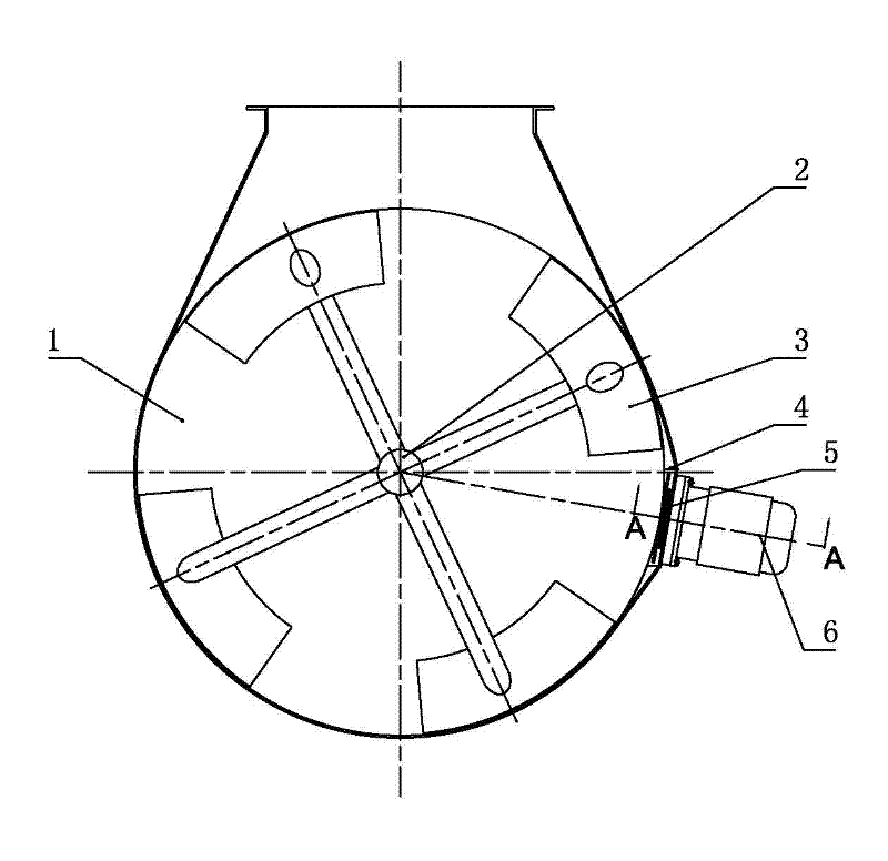
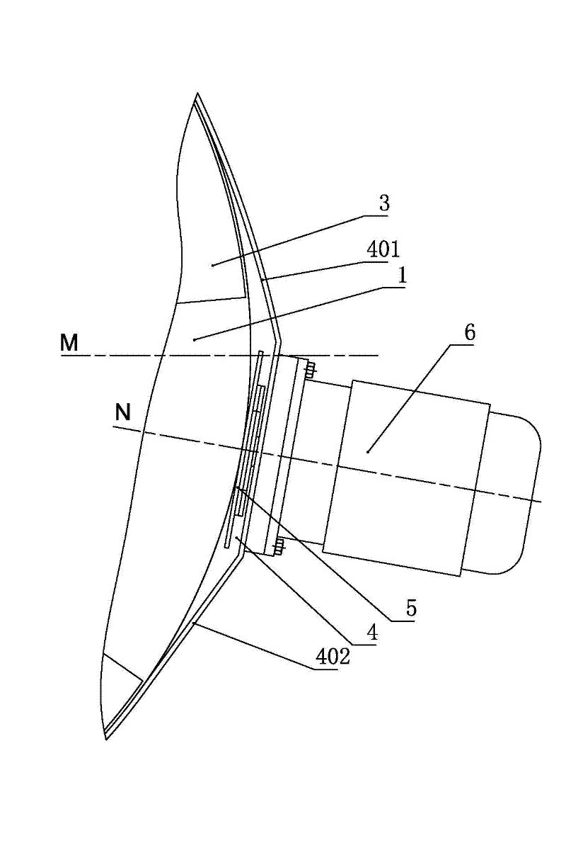
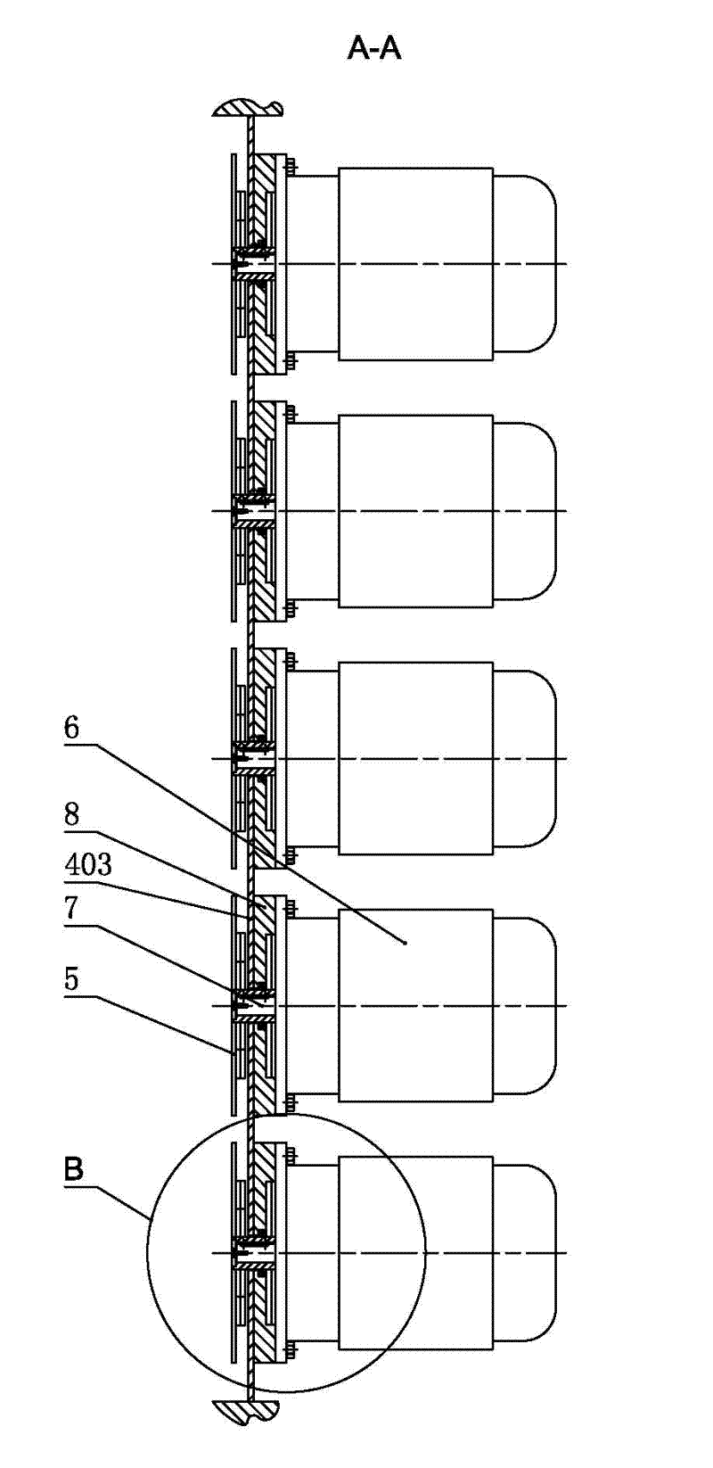
[0018] Such as figure 1 As shown in -5, the single-shaft paddle mixer of the present invention includes a horizontally arranged mixing chamber 1 and a rotor, the rotor is arranged in the mixing chamber 1, and the rotor is composed of a rotating shaft 2 and several paddles 3 arranged on the outer periphery of the rotating shaft , There is a gap between the inner wall of the mixing chamber and the outer edge of the paddle 3, so as to facilitate the rotation of the rotor to stir and mix the materials. The crushing chamber 4 extending outside, the upper and lower sides of the crushing chamber 4 are connected tangentially to the mixing chamber 1 through the material guide plates 401 and 402 respectively, forming a smooth transition connection. The crushing chamber 4 extends from one end of the mixing chamber 1 to the other end of the mixing chamber. 4, along the length direction of the crushing chamber, several hammer-knife groups 5 are arranged side by side. The rotary surfaces of...

Embodiment 2

[0021] The difference with the above-mentioned embodiment 1 is that each hammer knife group 5 includes a disc-shaped hammer blade 5b, and the outer edge of the disc-shaped hammer blade 5b is provided with several grooves 501, and the length direction of the groove 501 is Parallel to the axis of rotation of the disk-shaped hammer blade 5b.


PUM


Abstract

The invention discloses a homotaxial paddle mixer, which belongs to the field of feed processing machinery, and aims to solve the problem that the oil puddle is produced when oil is added into the mixing material. The device comprises a horizontal mixing chamber and a rotor, wherein the rotor is arranged in the mixing chamber, and comprises a rotating shaft and a plurality of paddles which are arranged at the periphery of the rotating shaft, a radial crushing chamber which extends out of the mixing chamber is arranged at one side of the mixing chamber and is positioned at the downward sides of the rotating directions of the paddles, the upper and the lower sides of the crushing chamber are in smooth transition connection with the mixing chamber, a plurality of hammering groups are arranged in parallel in the crushing chamber along the length direction of the crushing chamber, each hammering group comprises one or more than one hammering piece(s) which is(are) superposed, the hammering groups are installed on hammering shafts, and the hammering shafts are in transmission connection with drive motors which are arranged outside the crushing chamber in the one-to-one correspondence way. The homotaxial paddle mixer is safe and reliable, and has a good crushing effect on the oil puddle which is produced when oil is added into the mixing material, so the oil puddle in the material can be reduced, the material mixing efficiency is high, and the mixing is more uniform.

Description

technical field [0001] The invention relates to a single-shaft mixer in the field of feed machinery, in particular to a single-shaft mixer with a grease adding system. Background technique [0002] In the prior art, the single-shaft paddle mixer includes a horizontal mixing chamber and a rotor, the rotor is arranged in the mixing chamber, the upper side of the mixing chamber is provided with a feed port, and the lower side of the mixing chamber is provided with a switchable outlet. The material door and the rotor include a rotating shaft and a number of paddles arranged on the outer periphery of the rotating shaft. There is a certain gap between the inner wall of the mixing chamber and the outer edge of the paddles. When the rotor rotates, the paddles stir the materials so that different materials are mixed evenly. Then open the discharge door to discharge the material; when the mixer is adding oil or other liquids to the material for mixing, the material will agglomerate an...

Claims


Application Information

Patent Timeline
IPC IPC(8): B01F7/04B01F15/00B01F3/14B01F3/12B02C18/06B01F23/57
Inventor 华焜
Owner JIANGSU MUYANG GRP CO LTD
Learn More