Motorcycle engine exhaust valve rod

An engine and exhaust valve technology, which is applied in the direction of engine components, machines/engines, mechanical equipment, etc., can solve the problem of pulling the exhaust valve rod part 2, burning the exhaust valve rod, and not returning the exhaust valve rod in time. and other problems, to ensure that the metallographic structure and strength do not change, prevent breakage or damage to the top of the piston, prevent heat accumulation and sudden temperature rise

Inactive Publication Date: 2007-11-14
CHONGQING LIFAN INDUSTRIAL (GROUP) CO LTD
View PDF0 Cites 7 Cited by
  • Summary
  • Abstract
  • Description
  • Claims
  • Application Information

AI Technical Summary

Problems solved by technology

[0003] The working condition of the exhaust valve rod is very bad. It is directly in contact with the high-temperature gas burning in the cylinder, and it is seriously heated, while the heat dissipation (mainly depends on the moment when the head is seated, the heat is transferred to the cylinder head through the valve seat, and secondly, through the connection with the rod part. It is very difficult to dissipate part of the heat from the contacting valve guide, so the operating temperature is higher
Especially when the motorcycle is overloaded, the temperature of the exhaust valve stem head 1 will rise sharply, and a large amount of heat will accumulate in the exhaust valve stem head 1, which cannot be dissipated through the valve seat and valve guide in time, which will inevitably lead to exhaustion. The metallographic structure of the valve stem changes, and its strength also decreases. In this way, the outer circle of the exhaust valve stem part 2 is prone to strain, so that the exhaust valve stem does not return in time, resulting in the exhaust valve stem head being damaged. Part 1 touches the top of the piston, causing the exhaust valve stem to break or damage the top of the piston; It will form colloidal deposits with the rod part 2. The colloidal deposits hinder the reciprocating movement of the exhaust valve rod, and even stick to the exhaust valve rod, which will not only cause air leakage, but also easily burn the exhaust valve rod due to overheating. Early scrapping

Method used


Image

  • Motorcycle engine exhaust valve rod
  • Motorcycle engine exhaust valve rod

Examples


Embodiment Construction

[0014] Below in conjunction with accompanying drawing and embodiment the present invention will be further described:

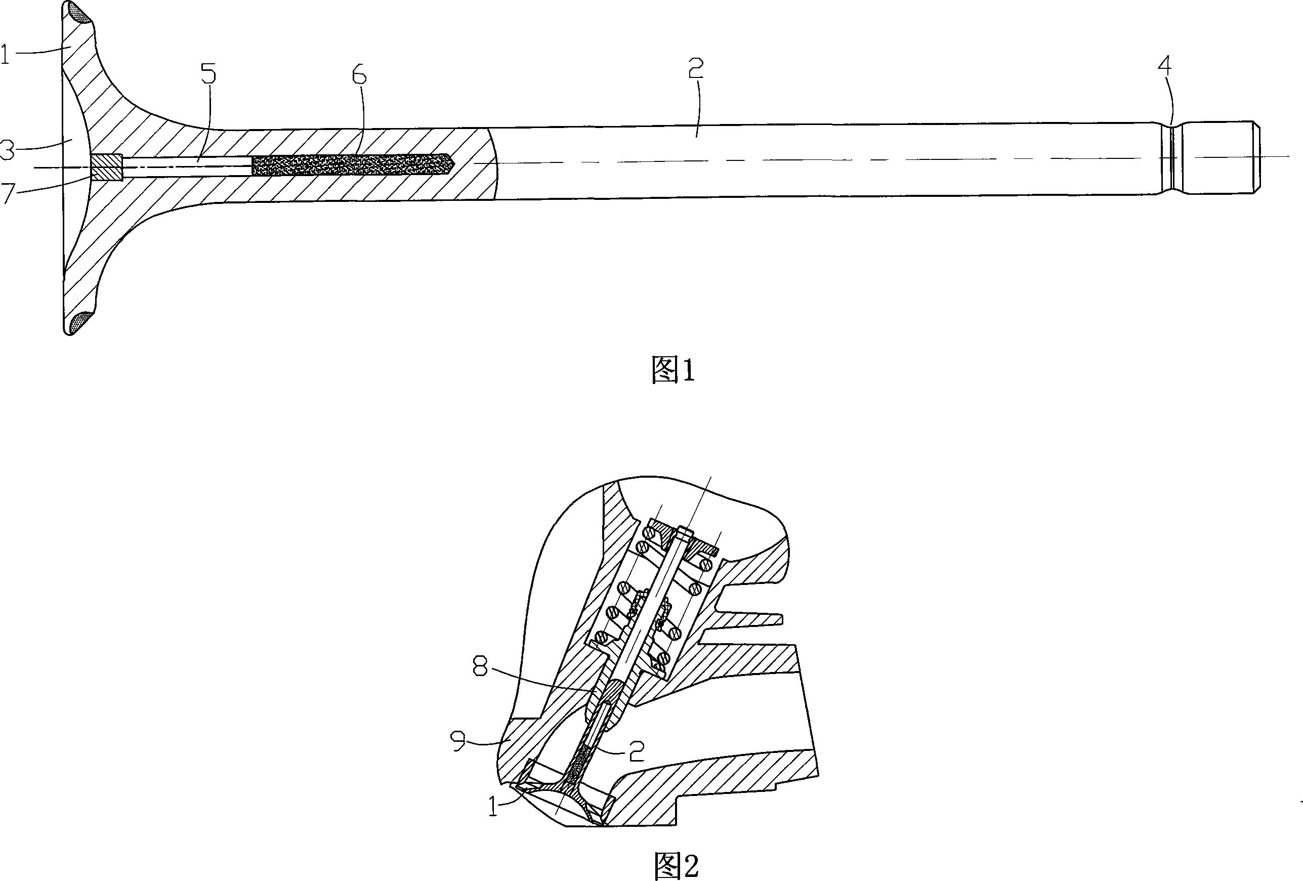
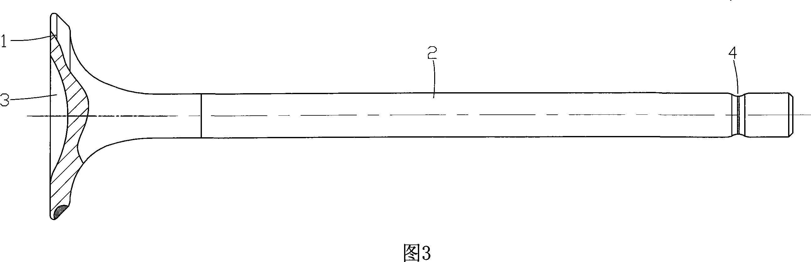
[0015] As shown in Figure 1, the present invention is made of parts such as head 1, rod 2, metal powder 6 and plug 7. The head 1 and the rod 2 are integrally structured, the rod 2 is installed in the valve guide 8 to play a guiding role, and an annular groove 4 is opened on the circumferential surface of one end of the rod 2 to install the locking member; the head 1 Located at the other end of the rod part 2, the axis lines of the two coincide. The head part 1 is a disc structure with a conical slope, which is used to close the exhaust passage of the cylinder head 9. Between the head part 1 and the rod part 2 A smooth transition connection is adopted, and an arcuate groove 3 is provided on the end surface of the head 1 . The groove bottom of the groove 3 is provided with an accommodating hole 5 extending along the rod portion 2, the center line of the accomm...


PUM


Abstract

The invention discloses a motorcycle engine exhaust valve stem which includes the head of one molding (1) and the rod (2). The circumference face at end of rod has a ring trough (4) and the head ( 1) located at the other end of the rod(2) , these two coinciding with the axis line. In the head (1) there is a groove(3), at the bottome of which has the capacity of home along rod part(2). The capacity of home(5) is filled by contents of sodium metal powder (6), and the Vice-home (5) Department of imports from Plug (7) Seal. This invention can timely release the heat on the head to the rod, then remove the heat from catheter. Thus it effectively prevents the head of the exhaust valve from suddenly warming and accumulating heat, and ensures the metallurgical structure and its intensity have no changes, eliminates disadvantagel caused by colloform sediment breaking upcoarse oil, so ensure the performance and the service life of exhaust valve stem.

Description

technical field [0001] The invention belongs to the technical field of motorcycle engines, and in particular relates to a motorcycle engine exhaust valve lever. Background technique [0002] The exhaust valve rod directly affects the sealing and exhaust performance of the motorcycle engine, and is an important part of the engine. The structure of the exhaust valve stem of a general-purpose motorcycle engine is shown in Figure 3. It consists of a head 1 and a rod 2. The exhaust valve stem head 1 is a disc with a conical slope, which is used to close the exhaust passage of the cylinder. , the end face of the head 1 is provided with a groove 3 with a bow-shaped section; the rod 2 is integrated with the head 1 and installed in the valve guide to play a guiding role. The rod 2 and the head 1 are connected by a smooth transition. The end of the rod 2 away from the head 1 is provided with an annular groove 4 for mounting the locking element. [0003] The working condition of the ...

Claims


Application Information

Patent Timeline
Patent Type & Authority Applications(China)
IPC IPC(8): F01L3/02
Inventor 王胜华
Owner CHONGQING LIFAN INDUSTRIAL (GROUP) CO LTD
Why Eureka
Try Eureka