Method for returning transfusion tube by simultaneously and correspondingly accepting pressure at two sides

An infusion tube and pressure technology, which is applied in the field of medical infusion equipment and medical equipment, and can solve problems affecting the service life of peristaltic infusion pumps, fatigue of infusion tubes, failure of peristaltic infusion pumps, etc.

Inactive Publication Date: 2011-04-27
BEIJINGKELLYMEDCO
View PDF8 Cites 4 Cited by
  • Summary
  • Abstract
  • Description
  • Claims
  • Application Information

AI Technical Summary

Problems solved by technology

The above-mentioned working principle and working process can be explained: each "shift fork piece" is all tens of millions of times, and many times from the beginning to the end, the infusion tube is "repeatedly squeezed in one direction before and after", which will inevitably lead to "extrusion". Fatigue of the infusion tube", so that the original circular infusion tube becomes "oblate" or "flat" after being "repeatedly squeezed", which undoubtedly causes the "infusion quantity and speed" "Irreparable "error", this irreparable "error" is not only a problem affecting the service life of the peristaltic infusion pump, but a serious problem of "infusion effect" as mentioned above, this irreparable "infusion The serious problem of "effect" -- it is unimaginable
For this "unthinkable" drawback, no matter whether it is a domestic or imported peristaltic infusion pump, it has not been solved. It is a technical problem that has plagued the industry for many years.

Method used


Image

  • Method for returning transfusion tube by simultaneously and correspondingly accepting pressure at two sides
  • Method for returning transfusion tube by simultaneously and correspondingly accepting pressure at two sides

Examples


Embodiment Construction

[0020] In the following, the "method for making both sides of the infusion tube return to the corresponding positions corresponding to receiving pressure" of the present invention will be described in detail in conjunction with the accompanying drawings of the description. As shown in the accompanying drawings:

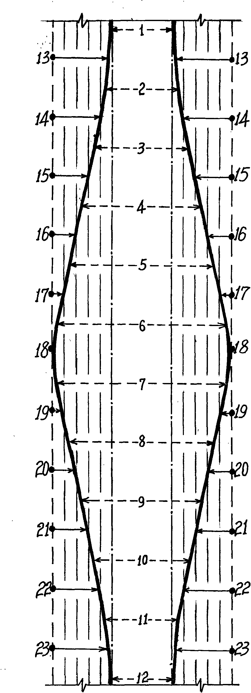
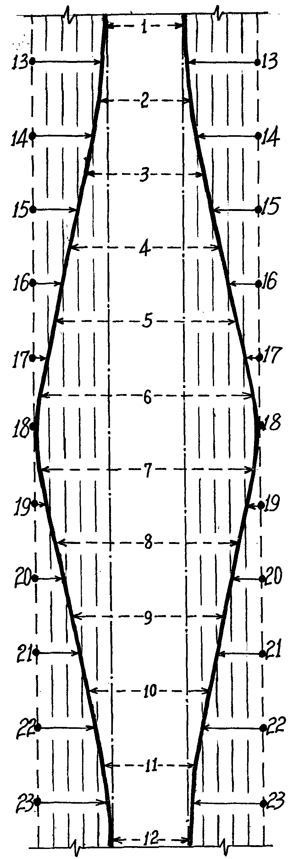
[0021] A method for returning both sides of the infusion tube corresponding to receiving pressure at the same time, including a spring plate that presses against the front side of the infusion tube, and also includes sliding in the slideway of the pump head housing in sequence to form a sinusoidal operation mode for the infusion. 12 fork pieces extruded on the rear side of the tube;

[0022] ①. On both sides of the infusion tube between every two shift forks, return pressure points for exerting pressure on both sides of the infusion tube are set in a corresponding manner, so as to form a pressure point for the two sides of the infusion tube. There are 22 return press...


PUM


Abstract

The invention provides a method for returning a transfusion tube by simultaneously and correspondingly accepting pressure at two sides, belonging to the technical field of medical equipment. The transfusion tube comprises a spring plate which is jacked at the front side face of the transfusion tube and 12 shifting fork plates which slide in a slide way of the shell of a pump head to form a sine curve to extrude the back side face of the transfusion tube; the two sides of the transfusion tube among every two shifting fork plates are jointly provided with 22 returning pressure points which are arranged on the shell of the pump head to apply equal pressures to the two sides of the transfusion tube, wherein the pressure is equal to 0-0.7MPa, is in inverse proportion to the pressure of each shifting fork plate, and changes along with the pressure of the former adjoining shifting fork plate; when the pressure of each shifting fork plate is changed, the returning pressure points apply the equal pressures to the two side faces of the transfusion tube, wherein the pressures have inverse direction and are corresponding to each other; the dynamic process that the two side faces of the transfusion tube can simultaneously receive the continuously-changed sine curve pressure is formed; and the dynamic process that the two side faces of the transfusion tube can timely obtain the sine curve pressure is formed when the transfusion tube receives the pressures of the shifting fork plates, so that the transfusion tube can be timely returned and can not be fatigued. The transfusion tube can be used for transfusion and can be returned.

Description

technical field [0001] The invention relates to a method for returning both sides of an infusion tube corresponding to receiving pressure at the same time, and relates to the technical field of medical devices; in particular, it relates to the technical field of medical infusion equipment; in particular, it relates to a method for returning both sides of an infusion tube to correspondingly receiving pressure at the same time field. Background technique [0002] In view of the objective needs of the patient's specific condition, a peristaltic infusion pump, a medical device specially used for intravenous infusion of the patient, is often used in the specific treatment process of the patient. For this kind of peristaltic infusion pump, there are extremely strict requirements on the quantity and speed of the patient's intravenous infusion per unit time; otherwise, the treatment effect may be affected, and even the life safety of the patient may be affected. The working princip...

Claims


Application Information

Patent Timeline
Patent Type & Authority Applications(China)
IPC IPC(8): A61M5/172A61M5/142
Inventor 毛爱民
Owner BEIJINGKELLYMEDCO
Why Eureka
Try Eureka