Emitter wire conditioning device with wear-tolerant profile

A technology for protecting a device and an emitter electrode, which is applied in the direction of cleaning method using tools, electrode structure, cleaning method and utensils, etc., can solve problems such as device failure, reduction of flashover voltage, reduction of efficiency, performance and reliability, etc.

Inactive Publication Date: 2012-03-28
TESSERA INC
View PDF5 Cites 2 Cited by
  • Summary
  • Abstract
  • Description
  • Claims
  • Application Information

AI Technical Summary

Problems solved by technology

Accumulation of this hazardous material can reduce efficiency, performance and reliability, cause sparking or reduce sparkover voltage, and cause unit failure

Method used


Image

  • Emitter wire conditioning device with wear-tolerant profile
  • Emitter wire conditioning device with wear-tolerant profile
  • Emitter wire conditioning device with wear-tolerant profile

Examples


Embodiment Construction

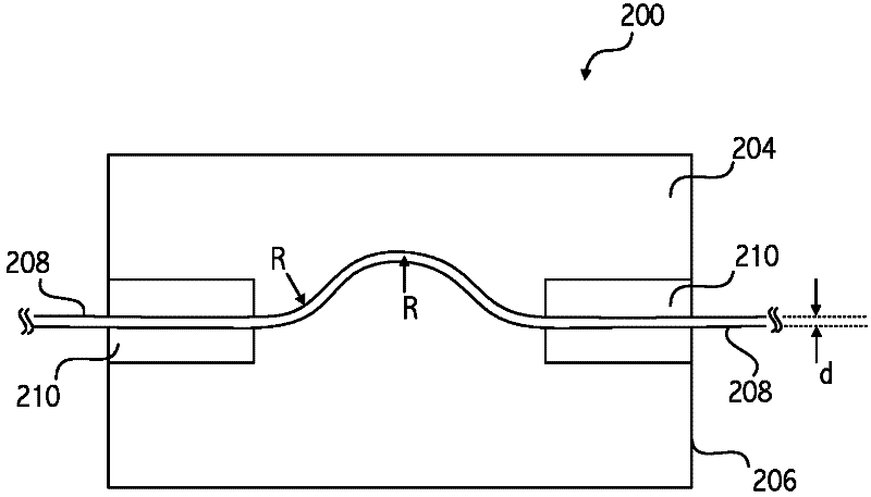
[0041] refer to figure 2 Cleaning device 200 includes complementary curvilinearly contoured cleaning pads 204 and 206 positioned to frictionally engage at least a portion of elongated emitter electrode 208 . In some embodiments, the conditioning device 200 can be moved to drive the conditioning pads 204 and 206 along the longitudinal extent of the emitter electrode 208, thereby removing harmful substances, such as silicon dendrites, surface contaminants, from the corresponding electrode surface. , particles or other debris. Contouring the guard pads 204 and 206 elastically deforms the electrode 208 into a curved shape, removes dendrites or other detrimental material from the electrode 208, or in other words, cleans or dresses the guard electrode.

[0042] The radius of the electrode bend shape is chosen to avoid plastic deformation of the electrode 208 . For example, the electrode diameter and the radius of the curved shape are selected such that the ratio between the elect...


PUM


Abstract

An apparatus for cleaning an emitter electrode in electrohydrodynamic fluid accelerator and precipitator devices via movement of a cleaning device including complementary contoured cleaning surfaces positioned to frictionally engage and elastically deform the emitter electrode. The opposing cleaning surfaces laterally distort an otherwise linear longitudinal extent of the electrode under tension. The opposing cleaning surfaces are subject to wear, but maintain frictional engagement despite wear depths that exceed a radius of the electrode due at least in part to the at least partially complementary surface contours engaging the electrode under tension. The cleaning device causes respective cleaning surfaces to travel along a longitudinal extent of the emitter electrode to remove detrimental material and optionally to condition the electrode to at least partially mitigate ozone, erosion, corrosion, oxidation, or dendrite formation on the electrode.

Description

technical field [0001] The present application generally relates to electrode conditioning in electrofluidic or electrostatic devices such as electrohydrodynamic accelerators and electrostatic precipitators. Background of the invention [0002] Many electronic and mechanically operated devices require airflow to help cool certain operating systems by convection. Cooling helps prevent the unit from overheating and improves long-term reliability. It is known that fans or other similar moving mechanical devices can be used to provide cooling airflow, but such devices typically have a limited operating life, generate noise or vibration, waste power, or have other design problems. [0003] The use of ion flow ventilation devices such as electrohydraulic (EHD) devices or electrohydraulic dynamic (EFD) devices can increase cooling efficiency and reduce vibration, power consumption, electronics temperature and noise generation. This can reduce overall device lifetime cost, device ...

Claims


Application Information

Patent Timeline
Patent Type & Authority Applications(China)
IPC IPC(8): B03C3/34
CPCB03C3/41B03C2201/14B03C3/743B08B1/008B03C2201/04
Inventor D·布朗斯汀P·贝茨G·高R·戈德曼E·尼恩M·舒维伯特Z·特莱纳G·亨浦司顿
Owner TESSERA INC
Why Eureka
Try Eureka