Clamping location pneumatic gripper

A pneumatic gripper, clamping and positioning technology, applied in the field of manipulators, can solve the problems of inaccurate positioning of manipulators, and achieve the effects of simple structure, precise positioning and reliable control

Inactive Publication Date: 2012-03-28
董旭
View PDF6 Cites 8 Cited by
  • Summary
  • Abstract
  • Description
  • Claims
  • Application Information

AI Technical Summary

Problems solved by technology

[0003] The present invention is to solve the problem that the positioning of the manipulator in the prior art is not accurate enough; it provides a pneumatic gripper for clamping and positioning; the structure is simple, the positioning is accurate, and the use is reliable

Method used


Image

  • Clamping location pneumatic gripper
  • Clamping location pneumatic gripper

Examples


Embodiment Construction

[0015] The present invention will be further described below in conjunction with the accompanying drawings and embodiments.

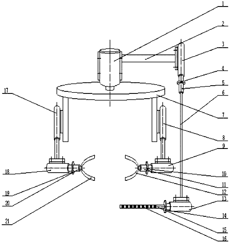
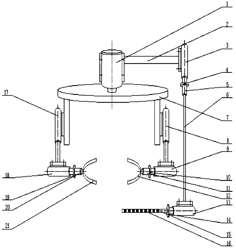
[0016] The pneumatic gripper for clamping and positioning, as shown in the figure, includes motor I1, fixed rod I2, cylinder I3, fixed baffle I4, motor II5, fixed rod II6, rotating plate 7, cylinder II8, cylinder III9, fixed baffle II10 , motor III11, gripper I12, cylinder IV13, fixed baffle III14, fixed rod III15, pressure sensor 16, cylinder V17, cylinder VI18, fixed baffle IV19, motor IV20, gripper II21, the housing of the motor I1 and cylinder I3 Connection; the shaft of the motor I1 is connected to the rotating plate 7, the shaft of the motor II5 is connected to the fixed rod II6, the motor III11 is connected to the claw I12, the motor IV20 is connected to the claw II21 respectively, and the pressure sensor 16 is connected to the fixed rod III15, The rod of the cylinder I3 is connected to the fixed baffle I4, the rod of the cylinder III9 is ​​conne...


PUM


Abstract

The invention discloses a clamping location pneumatic gripper, which comprises a motor I, a dead lever I, an air cylinder I, a fixed dam I, a motor II, a dead lever II, a rotary plate, an air cylinder II, an air cylinder III, a fixed dam II, a motor III, a gripper I, an air cylinder IV, a fixed dam III, a dead lever III, a pressure sensor, an air cylinder V, an air cylinder VI, a fixed dam IV, a motor IV and a gripper II, wherein the motor I is connected with the shell of the air cylinder I; the shaft of the motor I is connected with the rotary plate; the shaft of the motor II is connected with the dead lever II; the motor III is connected with the gripper I; the motor IV is connected with the gripper II; the pressure sensor is connected with the dead lever III; the lever of the air cylinder I is connected with the fixed dam I; the lever of the air cylinder III is connected with the fixed dam II; the lever of the air cylinder IV is connected with the fixed dam III; the lever of the air cylinder VI is connected with the fixed dam IV; the rotary plate is provided with the air cylinder II and the air cylinder V; the rods of the air cylinder II and the air cylinder V are respectively connected with the air cylinder III and the air cylinder VI; and the air cylinder III and the air cylinder VI are respectively connected with the motor III and the motor IV. The clamping location pneumatic gripper disclosed by the invention has a simple structure, accuracy in location and reliability in service.

Description

technical field [0001] The invention relates to a manipulator, in particular to a clamping and positioning pneumatic gripper. Background technique [0002] In the machining and injection molding industries, many stations are for picking up and positioning objects. This kind of operation is generally simple in action and highly repeatable. At present, many picking machines or manipulators have been designed for this demand, including electric, hydraulic, and pneumatic, etc. But the positioning of this kind of machinery or manipulator is not accurate enough at present. Contents of the invention [0003] The present invention aims to solve the problem of inaccurate positioning of the manipulator in the prior art; it provides a pneumatic gripper for clamping and positioning; the structure is simple, the positioning is accurate, and the use is reliable. [0004] In order to achieve the above object, the present invention adopts the following technical solutions: [0005] Pn...

Claims


Application Information

Patent Timeline
IPC IPC(8): B25J15/00
Inventor 董旭陈洪满申超杜志元常海铭
Owner 董旭
Why Eureka
Try Eureka