
Press buckle lock plate and buckle method

A snap-fit, plate technology, applied in the direction of floor, covering/lining, construction, etc., can solve problems such as inconvenience in construction, and achieve the effect of remarkable progress and convenient assembly and combination.

Active Publication Date: 2015-08-19
张家铭 +2
View PDF11 Cites 0 Cited by
  • Summary
  • Abstract
  • Description
  • Claims
  • Application Information

AI Technical Summary

Problems solved by technology

[0007] The problem to be solved by the present invention is to overcome some deficiencies in the prior art that the plate with locking function is inconvenient for construction during assembly

Method used


Image

  • Press buckle lock plate and buckle method
  • Press buckle lock plate and buckle method
  • Press buckle lock plate and buckle method

Examples


Embodiment Construction

[0071] The push-fit locking plate of the present invention has a rectangular shape and has a first plane as a surface, a second plane opposite to the first plane, and four sides, wherein at least two of the opposite sides are respectively formed with protrusions. Tenon and tenon.

[0072] The present invention will be further described below in conjunction with the accompanying drawings and preferred embodiments.

[0073] First preferred embodiment:

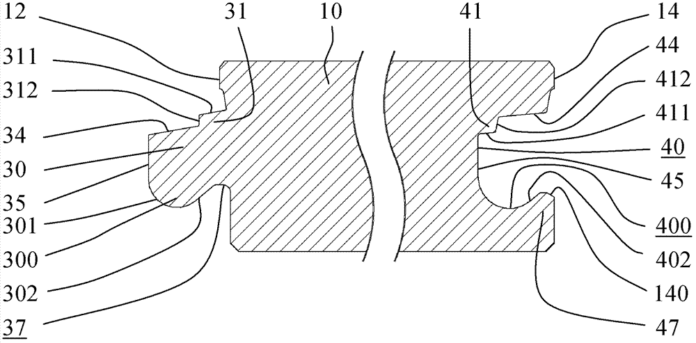
[0074] by figure 1As shown in the side view cross-sectional structural schematic diagram of the first preferred embodiment of the push-fit locking plate of the present invention, a tenon 30 protruding outward from the side 12 is formed on the side 12 of the plate unit 10. The tenon 30 has a top surface 34 and an outer side 35. A lower projection 300 is provided on the lower edge of the tenon 30. An outer slope 301 is formed outside the lower projection 300, and an inner slope 301 is formed inside the lower projection 300. The ...


PUM


Abstract

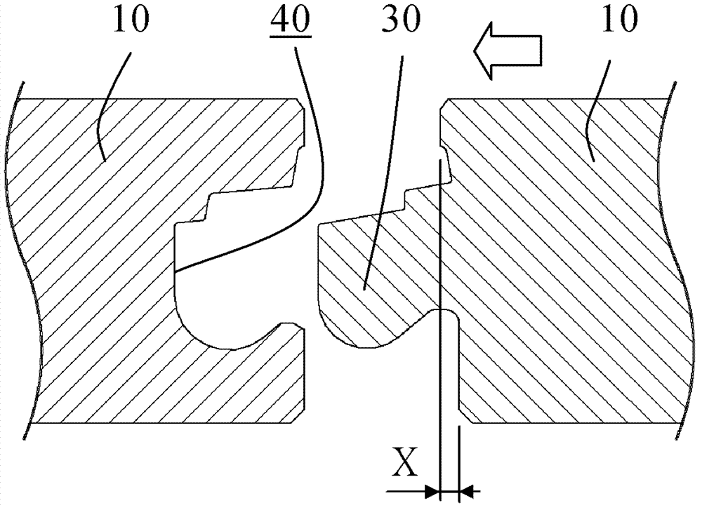
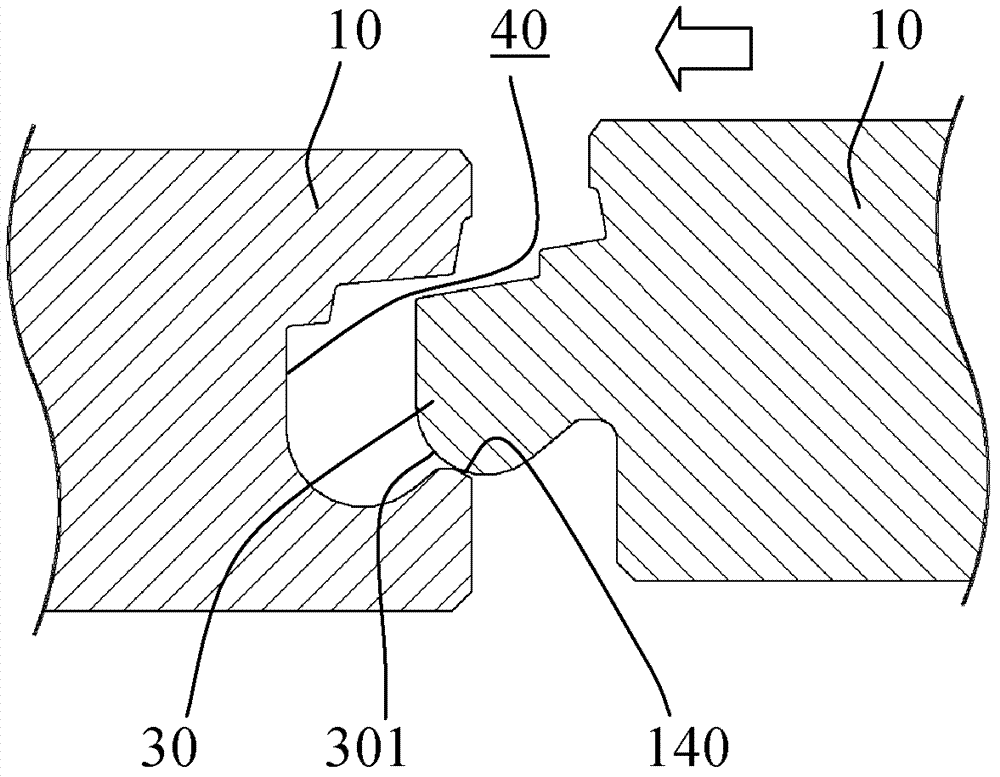
A pressing type lock plate and locking method thereof are provided, wherein the plate are assembled by rectangular plate units (10), and two opposite sides (12,14) of the plate unit (10) are respectively provided with a convex tenon (30) and concave groove (40). A bottom edge of the convex tenon (30) is formed with a lower protrusion (300) provided with an inside inclined surface (302), a bottom surface of the concave groove (40) is formed with a lower groove (400), a lock piece (47) is formed between the lower groove (400) and a lower side wall (142), and the lower groove (400) is placed with an inclined bottom wall (402) located inside of the lock piece (47). A first raised strip (41) is shaped at a juncture of an upper groove wall (44) and an inner groove wall (45) of the concave groove (40), and one side surface of which is formed with a bearing surface (412). The locking method of the lock plate comprises: pushing a plate unit(10) with a convex tenon (30) toward another plate unit (10) with a concave groove (40) in the same plane, so that the convex tenon (30) entering into the concave groove (40) and then an outer surface (35) of the convex tenon (30) bearing against the bearing surface (412) of the first raised strip (41) in the concave groove (40), at the same time, the lower protrusion (300) of the convex tenon (30) entering into a scope over the lower groove (400) of the concave groove (40), making the inside inclined surface (302) of the lower protrusion (300) of the convex tenon (30) contact with the inclined bottom wall (402) of the lower groove (400) of the concave groove (40), then the plate units (10) being locked together by pressing.

Description

Technical field: [0001] The invention relates to a locking board, which can be a board that can be spliced ​​and assembled, such as a floor or a wall board. In particular, a tenon and a tenon are arranged on the side of the board unit so that the board units can be locked together when they are spliced. of plates. Background technique: [0002] The tongue-and-groove floor has been used for quite a long time, and its assembly structure has also been applied to wall panels or similar boards. Let’s take the floor as an example. The tongue-and-groove floor is easy to assemble and can connect and combine board units, so it is widely consumed It is used by those who use it, and related companies spare no effort to carry out research and improvement, hoping to design more practical products. According to the Chinese invention patent application CN200610201430.5, it is an improved structure of the traditional grooved floor , it can be combined by two panel units touching on the sam...

Claims


Application Information

Patent Timeline
Patent Type & Authority Patents(China)
IPC IPC(8): E04F13/076E04F15/02
CPCE04F2201/0115E04F15/02038
Inventor 张家铭张棋惠许倍嘉
Owner 张家铭
Learn More