Reversible lock body

A lock body and reversing gear technology, applied in the field of mechanical locks, can solve the problems of increasing the overall cost and inconvenient use, and achieve the effects of cost saving, convenient installation and maintenance

Inactive Publication Date: 2013-10-23
CMECH (GUANGZHOU) INDUSTRIAL LTD
View PDF6 Cites 0 Cited by
  • Summary
  • Abstract
  • Description
  • Claims
  • Application Information

AI Technical Summary

Problems solved by technology

In the prior art, the lock bar is generally driven by the transmission bar connected to the unlocking module, and finally the lock bar is inserted into the upper and lower parts of the door frame to lock the door in the vertical direction. In the above process, the lock bars inserted into the upper and lower parts of the door frame move in opposite directions, but in the current mechanical lock body, the drive bar drives the lock bar in only one direction, that is, the drive bar moves in a certain direction, and the lock bar also moves in the corresponding direction. Direction movement, in order to achieve the effect of different lock bars moving in opposite directions at the same time, people usually add a reversing mechanism outside the lock body, but adding a reversing structure not only increases the overall cost, but also needs to reserve additional space on the door body. space, extremely inconvenient during use

Method used


Image

  • Reversible lock body
  • Reversible lock body
  • Reversible lock body

Examples


Embodiment Construction

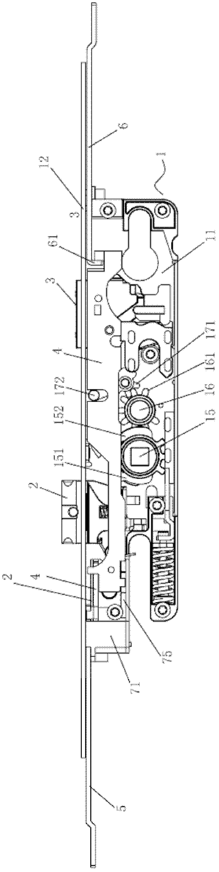
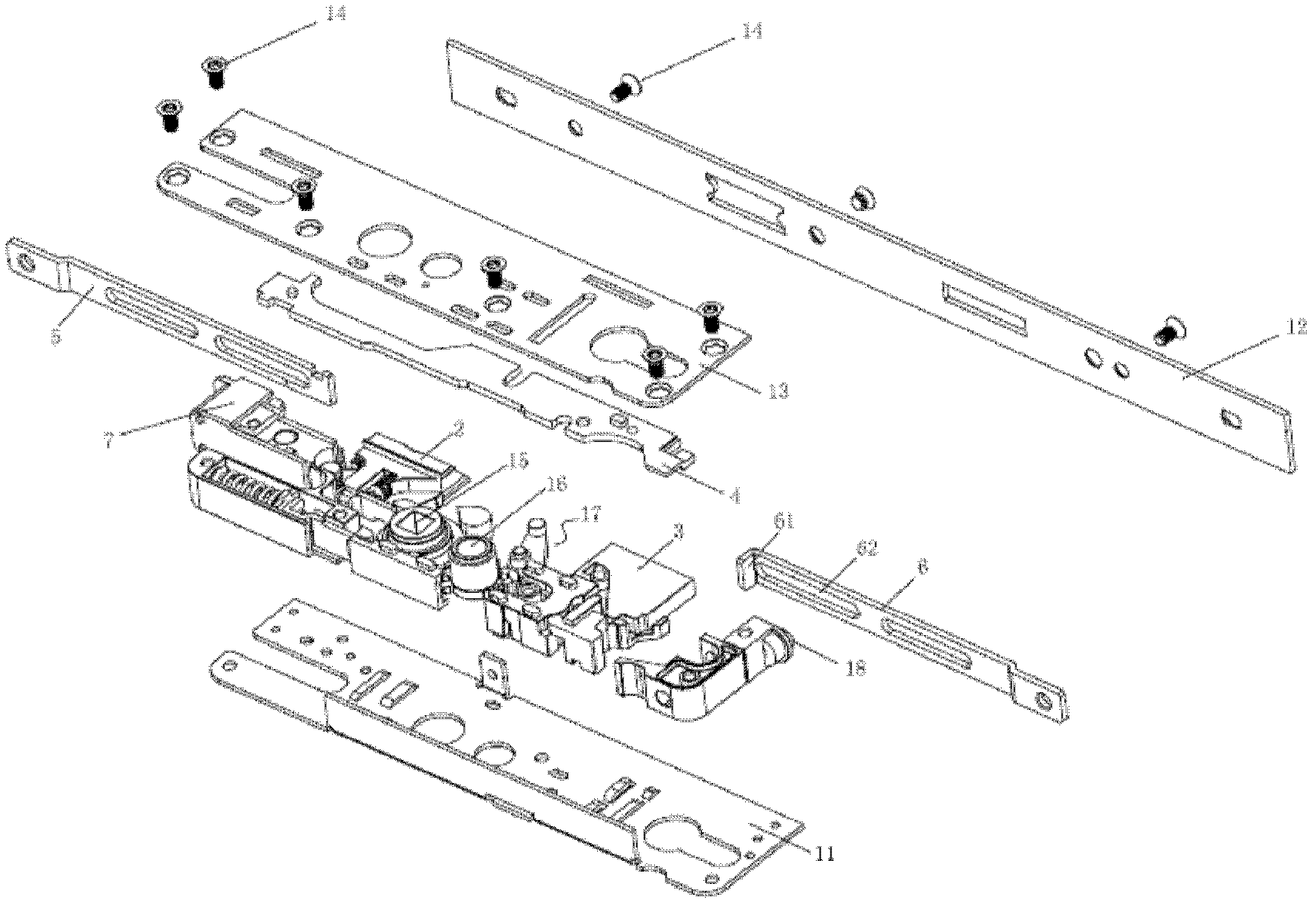
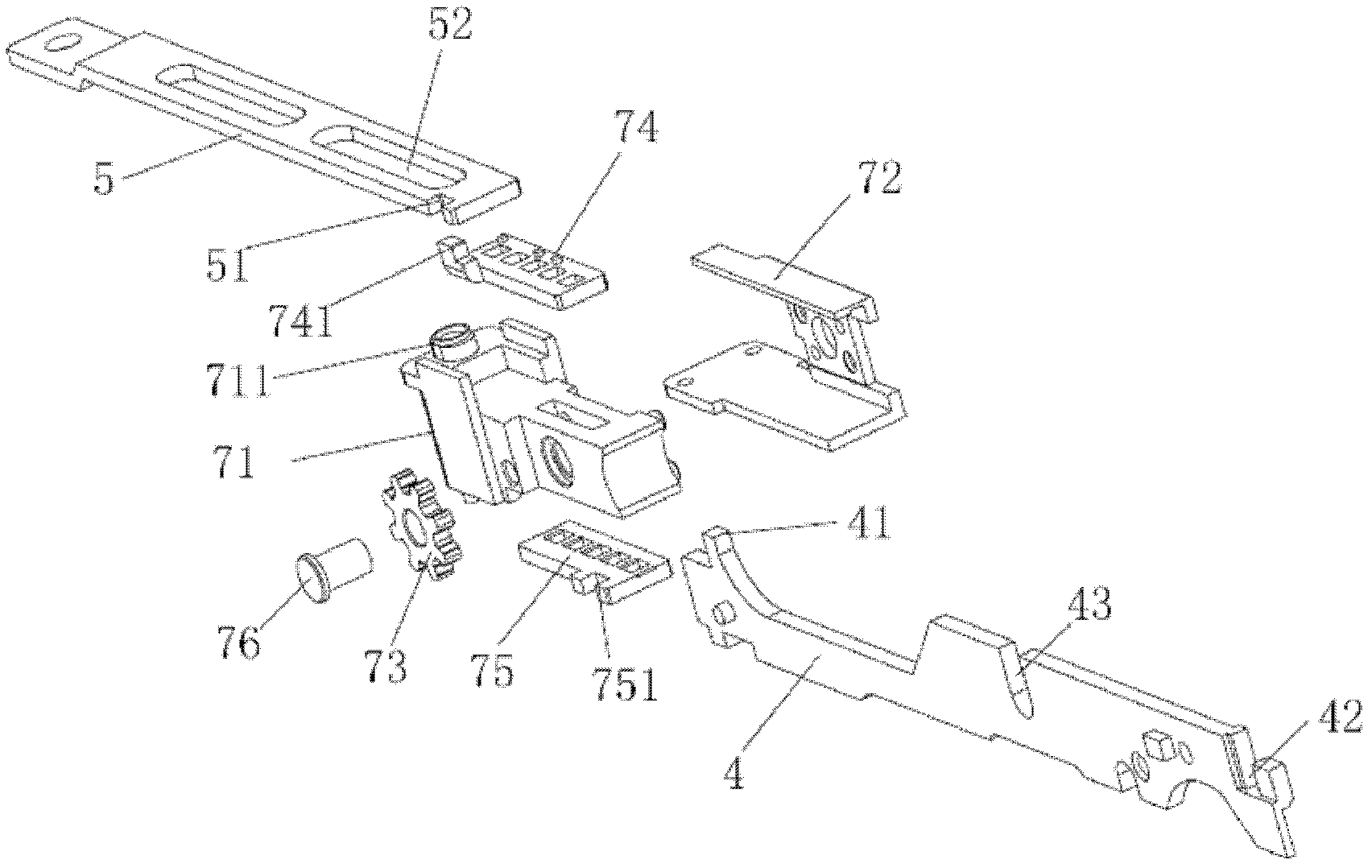
[0020] Below in conjunction with accompanying drawing and specific implementation, the present invention will be further described:

[0021] see Figure 1 to Figure 4 , the reversing lock body of the present invention includes a lock body shell 1 with a built-in cavity, the lock body shell includes a bottom plate 11 and a cover plate 13, wherein the cover plate 13 is consolidated with the bottom plate 11 by screws 14, and the lock body shell 1 is in A panel 12 is arranged close to the end side of the door frame, and the oblique tongue 2 and the square tongue 3 are arranged on the telescopic panel 12. An unlocking dial 16 that can be driven by a key is arranged in the above-mentioned cavity, and a rotating dial is connected with the unlocking dial 16. 15. The rotating block 15 cooperates with the sector gear 151 of the unlocking block 16 through the second interference block 152, and drives the oblique tongue 2 through the first interference block 151, and is connected with the...


PUM


Abstract

The invention relates to a reversible lock body comprising a lock body shell which is internally equipped with a containing cavity, and an inclined tongue and a square tongue which stretch out from one side of the lock body shell, wherein an unlocking shifting block capable of being driven by a key is arranged in the containing cavity; a rotary shifting block for driving the inclined tongue is arranged by means of being connected with the unlocking shifting block; a driving deflector rod is further arranged by means of being connected with the unlocking shifting block; a transmission bar which does a linear movement with the swinging of the driving deflector rod is arranged by means of being connected with the driving deflector rod; and one end of the transmission bar is connected with a first locking bar, and the other end of the transmission bar is connected with a second locking bar through a reversing gear assembly capable of changing the transmission direction of the transmission bar. According to the reversible lock body, no extra reserving structure is added, and simultaneously, reverse driving of the first locking bar and the second locking bar is realized so that a door lock is locked in a vertical direction. Therefore, the cost is saved, and the reversible lock body is more convenient and fast to install and maintain and is a mechanical lock body with compact structure and good practicability.

Description

technical field [0001] The present invention relates to a mechanical lock, in particular to a reversible lock body. Background technique [0002] In the prior art, the mechanical lock installed on the door can lock the door by controlling the expansion and contraction of the oblique tongue and the square tongue. The oblique tongue and the square tongue move back and forth in the horizontal direction. In the door, the door lock not only needs to lock and cooperate with the door frame at the end face where the oblique tongue and square tongue are located, but also needs to be locked with the door frame at the top and bottom of the door, so as to achieve the effect of three-sided protection. In the prior art, the lock bar is generally driven by the transmission bar connected to the unlocking module, and finally the lock bar is inserted into the upper and lower parts of the door frame to lock the door in the vertical direction. In the above process, the lock bars inserted into ...

Claims


Application Information

Patent Timeline
Patent Type & Authority Patents(China)
IPC IPC(8): E05B63/14E05B15/00
Inventor 吴丰庆
Owner CMECH (GUANGZHOU) INDUSTRIAL LTD
Why Eureka
Try Eureka