
FPGA (Field Programmable Gate Array)-based spike potential signal parallel detection device and method

A signal detector and spike technology, which is applied in the field of FPGA-based spike signal parallel detection device, can solve the problems of parallel real-time detection of multi-channel spike signals, etc.

Active Publication Date: 2012-03-28
ZHEJIANG UNIV
View PDF2 Cites 8 Cited by
  • Summary
  • Abstract
  • Description
  • Claims
  • Application Information

AI Technical Summary

Problems solved by technology

However, in the prior art, the general use of computers for the detection and processing of spike signals cannot meet the current requirements for parallel real-time detection of multi-channel spike signals.

Method used


Image

  • FPGA (Field Programmable Gate Array)-based spike potential signal parallel detection device and method
  • FPGA (Field Programmable Gate Array)-based spike potential signal parallel detection device and method
  • FPGA (Field Programmable Gate Array)-based spike potential signal parallel detection device and method

Examples


Embodiment 1

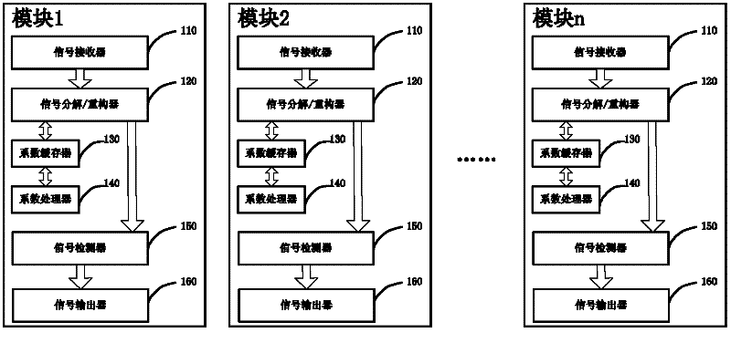
[0056] Such as figure 1 As shown, an FPGA-based spike signal parallel detection device is composed of n parallel modules, and each module includes: a signal receiver 110, a signal decomposition / reconstructor 120, a coefficient buffer 130, and a coefficient processor 140 , a signal detector 150 and a signal outputter 160.

[0057] The signal receiver 110 controls the reception of the signal sequence to be detected by judging the working state of the signal decomposing / reconstructing device 120. When the working state of the signal decomposing / reconstructing device 120 is idle, the signal receiver 110 receives the signal sequence to be detected and transmit it to the signal decomposer / reconstructor 120;

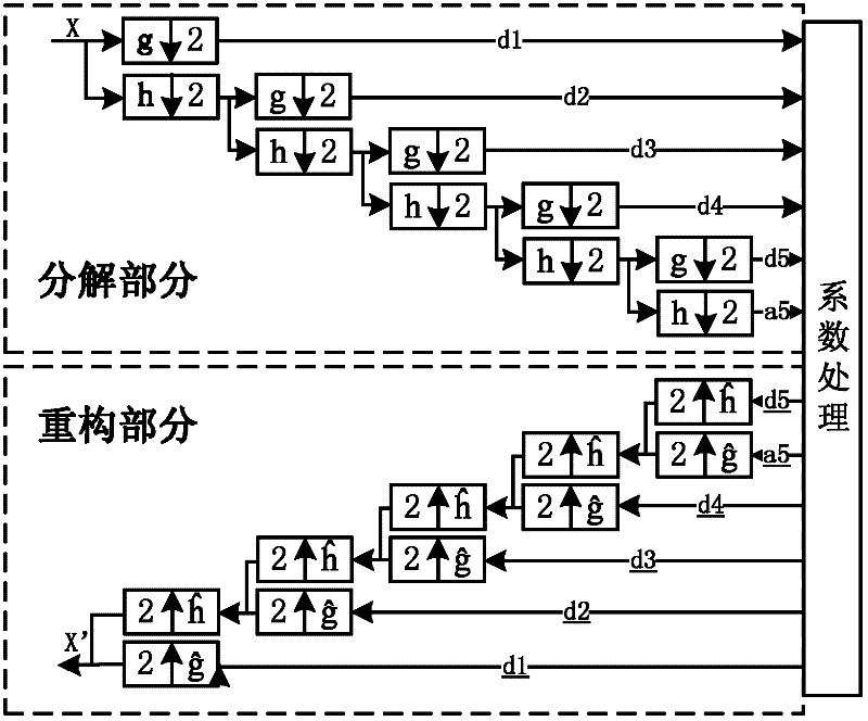
[0058] The signal decomposition / reconstruction unit 120, on the one hand, receives and decomposes the signal sequence to be detected transmitted by the signal receiver 110, sends the decomposed coefficient sequence to the coefficient buffer 130, and receives the signal sequenc...


PUM


Abstract

The invention discloses an FPGA (Field Programmable Gate Array)-based spike potential signal parallel detection device and a method. The device comprises parallel modules, wherein each module comprises a signal receiver, a signal decomposition / reconfiguration device, a coefficient buffer, a coefficient processor, a signal detector and a signal output device. The method comprises the following steps of: receiving a signal sequence to be detected, and decomposing the signal sequence to be detected to obtain a decomposed coefficient sequence; and processing the decomposed coefficient sequence, carrying out signal sequence reconstruction to the processed coefficient sequence, detecting the reconstructed signal sequence to obtain a spike potential signal, and outputting the spike potential signal. According to the invention, the signal processing speed is improved by realizing the operation mode of the pipeline processing of the signal decomposition / reconstruction, and the multi-channel parallel detection is realized by a modularized design of the FPGA-based single-channel spike potential signal parallel detection device, so that the processing efficiency of a system is improved.

Description

technical field [0001] The invention belongs to the field of implantable brain-computer interface, and in particular relates to an FPGA-based spike signal parallel detection device and method. Background technique [0002] In the implantable brain-computer interface technology, while recording the spike, the noise in the environment must be brought into the recording signal. At the same time, there is also noise interference in the electronic recording equipment, even including environmental interference in the laboratory. . However, the amplitude of the neural signal is very weak. When the neural signal is amplified by the amplifying circuit, the noise is inevitably amplified at the same time. Therefore, the signal obtained in the experimental record is a signal seriously disturbed by the noise. [0003] Separating spikes from background noise and obtaining useful neuron information is the purpose of spike detection, and it is the first step in the preprocessing of neural ...

Claims


Application Information

Patent Timeline
Patent Type & Authority Applications(China)
IPC IPC(8): H04L25/03H04L25/02
Inventor 陈耀武祝晓平田翔
Owner ZHEJIANG UNIV
Learn More