Air sealing member capable of opening air valve naturally and manufacturing method of air sealing member

A technology of air sealing body and manufacturing method, which is applied in the direction of preventing mechanical damage, container, transportation and packaging, etc., and can solve the problem that the air sealing body does not have the function of automatically opening the air inlet, cannot open the air passage inlet, and cannot multiple The air column is inflated at the same time, etc.

Inactive Publication Date: 2012-04-04
KUNSHAN AIRBAG PACKING CORP
View PDF8 Cites 10 Cited by
  • Summary
  • Abstract
  • Description
  • Claims
  • Application Information

AI Technical Summary

Problems solved by technology

However, because the check valves of this structure are independent of each other, each air column is inflated separately, and multiple air columns cannot be inflated at the same time. Moreover, it is quite cumbersome to manufacture, and each check valve must be placed one by one. Heat-sealing is carried out at the predetermined position in the air column. Once the position of the check valve or the adhesive position of the heat-sealing mold is shifted, the check valve cannot be fixed in the air column, or the inlet at the top exceeds the heat-sealing mold Adhesive heat sealing line will cause the gas to be filled into the inflatable channel. Although the inflatable channel expands, the check valve cannot be opened with the expansion of the inflatable channel, resulting in the gas not being able to be inflated into the air column.
[0004] Another kind of air sealing body structure is disclosed in Taiwan Patent No. 00587049 "The installation structure of the switch valve of...

Method used


Image

  • Air sealing member capable of opening air valve naturally and manufacturing method of air sealing member
  • Air sealing member capable of opening air valve naturally and manufacturing method of air sealing member
  • Air sealing member capable of opening air valve naturally and manufacturing method of air sealing member

Examples


Embodiment Construction

[0041] In order to make the object, technical solution and advantages of the present invention clearer, the present invention will be described in detail below with reference to the accompanying drawings and specific embodiments.

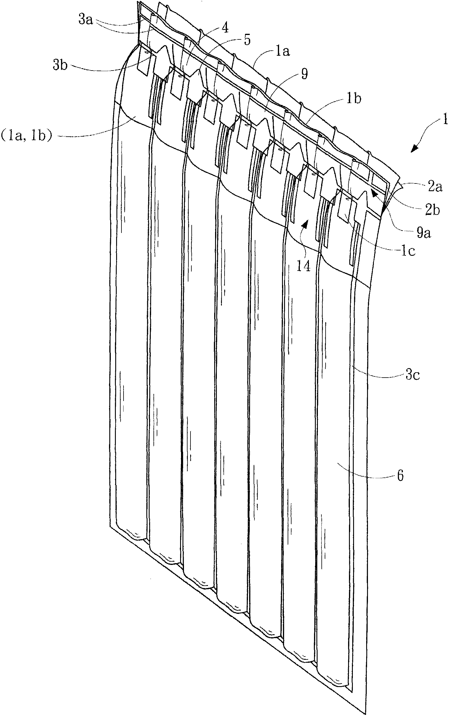
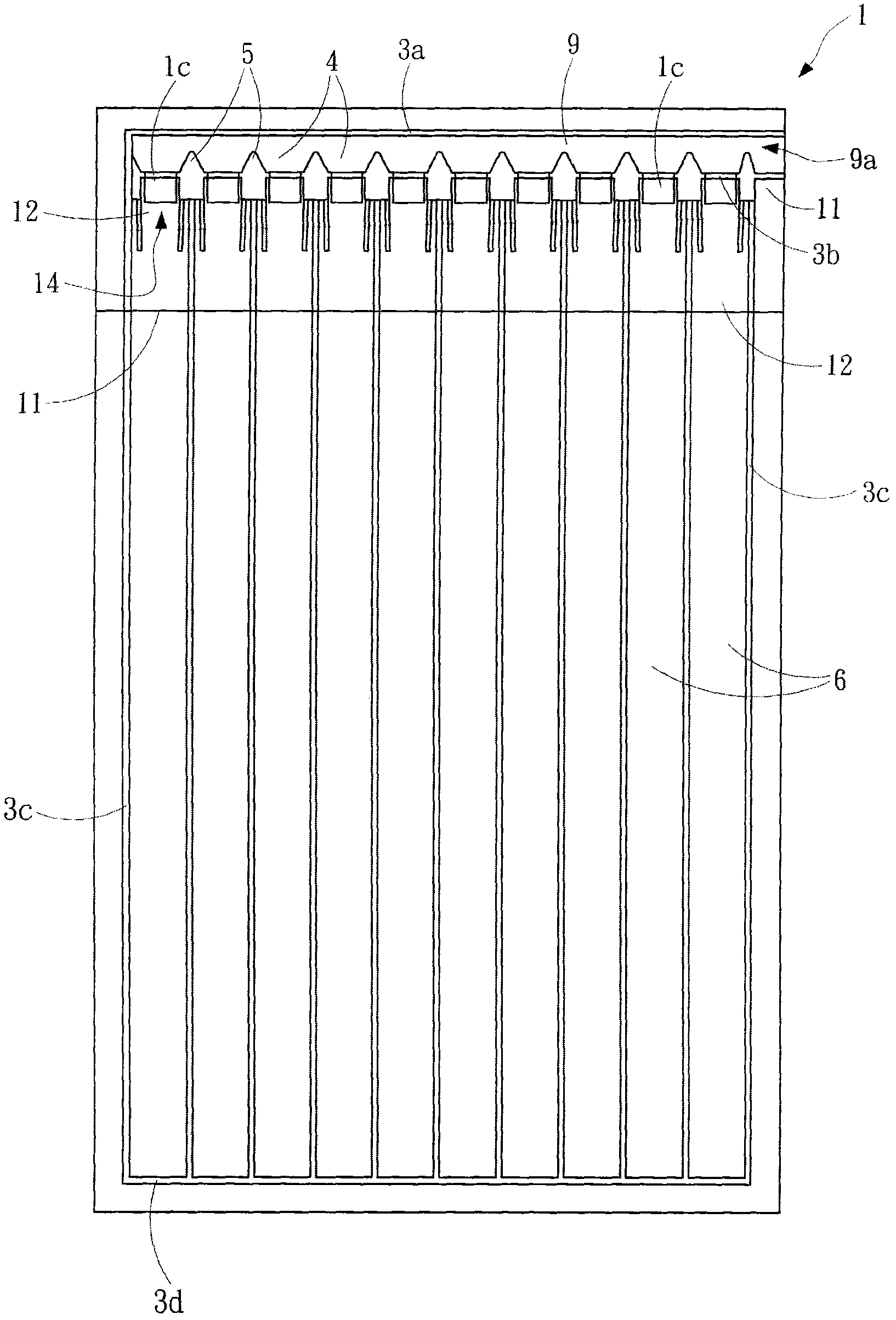
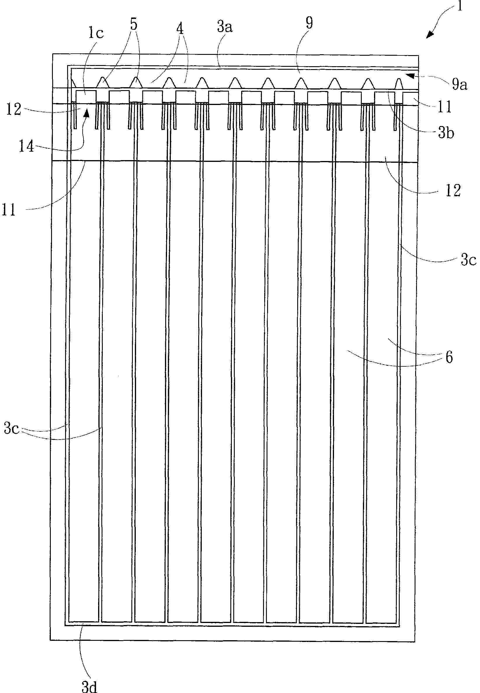
[0042] see figure 1 , Figure 2A , Figure 2B , image 3 and Figure 4 As shown, it is used to illustrate the first embodiment of the air sealing body of the natural open air valve of the present invention.

[0043] The air sealing body 1 of the present invention with a naturally open air valve includes: two outer films 2a and 2b, two inner films 1a and 1b, a heat-resistant material 1c, an inflatable channel 9, a plurality of air columns 6, and a plurality of heat-sealing areas Block 5.

[0044] Wherein, two outer membranes 2a and 2b are stacked up and down.

[0045] The two inner membranes 1a and 1b are interposed between the two outer membranes 2a and 2b, and placed slightly lower on the inner top of the two outer membranes 2a and 2b. The wi...


PUM


Abstract

The invention provides an air sealing member capable of opening an air valve naturally and a manufacturing method of the air sealing member. A heat-resisting material is firstly coated in a reserved area between two inner membranes, the two inner membranes are overlapped between two outer membranes, an inflatable channel and an air column are formed by means of heat sealing, air inlets are formedat the parts of the two inner membranes, on which the heat-resisting material is coated, by means of heat sealing, a plurality of heat sealing blocks are formed in the inflatable channel by adhering by means of heat sealing, wherein the plurality of heat sealing blocks are tapered gradually from one side close to a first horizontal heat sealing line to the other side. In an air inflation process,the two outer membranes of the inflatable channel are pulled outwards in a vertical direction, the inflatable channel is tightened in a horizontal direction because of fall formed by the heat sealingblocks, the two inner membranes are squeezed by the multiple heat sealing blocks to be pulled outwards, and thus the air inlets are opened; after air enters the air column, the two inner membranes are pressed to close the air column. Therefore the air sealing member can automatically open the air inlets to realize continuous air inflation in the air inflation process, and the purpose of saving air inflation time is achieved.

Description

technical field [0001] The invention relates to the technical field of packaging, in particular to an air sealing body with a naturally open air valve and a manufacturing method thereof. Background technique [0002] The air-sealed body is made of resin film, which is heat-sealed to form an air column in a sealed state, and is equipped with an inflation port for inflation. When the gas is filled into the air column through the inflation port, the air-sealed body can be used for inner packaging as a buffer material. [0003] Known air-tight structure such as the patent of Japanese utility model kaiping No. 5-95851 "sealed bag for fluid" is respectively provided with mutually independent check valves in each air column, and the inflow port at the top of each check valve is connected to the The heat-sealed lines are aligned and glued together, and when the gas is filled into the inflatable channel, the inflatable channel expands to open the check valve so that the gas can be i...

Claims


Application Information

Patent Timeline
IPC IPC(8): B65D81/03
Inventor 廖耀鑫廖国雄尹静雯廖庭玉
Owner KUNSHAN AIRBAG PACKING CORP
Why Eureka
Try Eureka