Service brake system for wheel loader

A wheel loader, service braking technology, applied in the direction of brakes, brake components, brake transmission devices, etc., can solve the problems of slow brake response of brake fluid and brake failure, etc.

Pending Publication Date: 2020-10-20
龙工(上海)机械制造有限公司
View PDF0 Cites 3 Cited by
  • Summary
  • Abstract
  • Description
  • Claims
  • Application Information

AI Technical Summary

Problems solved by technology

[0004] The technical problem to be solved by the present invention is: the brake fluid of the exis...

Method used


Image

  • Service brake system for wheel loader
  • Service brake system for wheel loader
  • Service brake system for wheel loader

Examples


Embodiment Construction

[0019] In order to make the present invention more comprehensible, preferred embodiments are described in detail below with accompanying drawings.

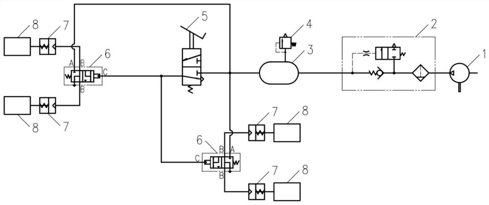
[0020] Such as figure 1 As shown, a service brake system for wheel loaders of the present invention includes an air compressor 1, an unloading valve 2, an air storage tank 3, a safety valve 4, an air brake valve 5, a relay valve 6, a brake Power air chamber 7 and brake, and brake adopts air pressure disc brake 8. The air compressor 1 is connected to the air storage tank 3 through the unloading valve 2, and the high-pressure gas output by the engine drives the air compressor 1 enters the air storage tank 3 through the unloading valve 2, and a safety valve 4 is installed on the air storage tank 3 to limit the maximum pressure of the system . The outlet of the air reservoir 3 is respectively connected to the air inlet of the air brake valve 5 and the air inlet A of the relay valve 6, and the air outlet of the air brake valve 5 is c...


PUM


Abstract

The invention discloses a service brake system for a wheel loader. The system comprises an air compressor, an unloading valve, an air cylinder and a safety valve. The air compressor is connected withthe air cylinder through the unloading valve; the safety valve is arranged on the air cylinder and is used for limiting the highest pressure of the system. The service brake system is characterized byfurther comprising an air brake valve, a relay valve, a brake air chamber and a brake, an outlet of the air cylinder is connected with an air inlet of the air brake valve and an air inlet of the relay valve, an air outlet of the air brake valve is connected with a control air pressure input port of the relay valve, and an air outlet of the relay valve is connected with the brake through the brakeair chamber. The system cancels the brake fluid to thoroughly solve a gasification problem of the brake fluid and improve the safety of the service brake system. The relay valve is used in the system, the position is reasonably arranged, the inflation time of a brake air chamber is shortened, the brake lag time is shortened, and brake is more sensitive.

Description

technical field [0001] The invention relates to a service brake system for a wheel loader, which belongs to the technical field of loaders. Background technique [0002] At present, the wheel loaders on the market generally use the air-push oil brake system to complete the service brake function of the vehicle. The high-pressure gas output by the engine driven air compressor enters the air storage tank through the unloading valve, and a safety valve is installed on the air storage tank to limit the maximum pressure of the system. When the brake pedal is stepped on for braking, the high-pressure gas enters the front and rear booster pumps through the air brake valve. to achieve vehicle braking. Release the brake pedal to release the brake. [0003] The air-push oil service brake system is cheap, but has high requirements for use and maintenance. The operating conditions of the loader require frequent braking. Generally, 4 to 6 times of braking are required within 60 secon...

Claims


Application Information

Patent Timeline
IPC IPC(8): B60T13/26B60T17/04B60T17/06B60T1/06E02F9/20
CPCB60T13/26B60T17/04B60T17/06B60T1/065E02F9/20E02F9/2083
Inventor 郭宏广张寒杉吴承鑫索沛沛叶筱娟
Owner 龙工(上海)机械制造有限公司
Why Eureka
Try Eureka