Siphon pedestal pan without water ring

A siphonic, toilet technology, applied in flushing toilets, water supply devices, flushing equipment with water tanks, etc., can solve the problems of large flushing volume and poor flushing effect, and achieve strong flushing, clean cleaning, and simple production process. Effect

Active Publication Date: 2012-04-04
GUANGDONG HEGII SANITARY WARES CO LTD
View PDF14 Cites 14 Cited by
  • Summary
  • Abstract
  • Description
  • Claims
  • Application Information

AI Technical Summary

Problems solved by technology

[0015] Most of the existing suction toilets are launched in the vortex type, which can achieve a relatively good flushing effect, but a relatively large amount of flushing water

Method used


Image

  • Siphon pedestal pan without water ring
  • Siphon pedestal pan without water ring
  • Siphon pedestal pan without water ring

Examples


specific Embodiment approach 2

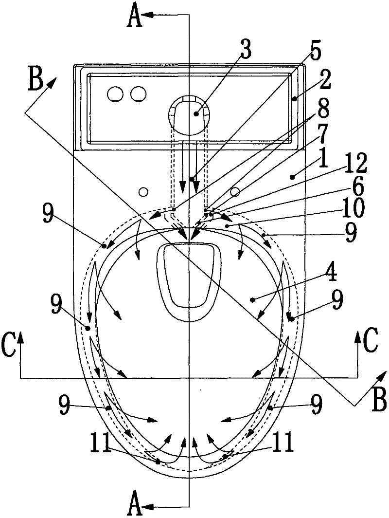
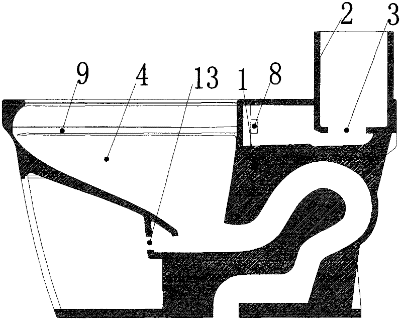
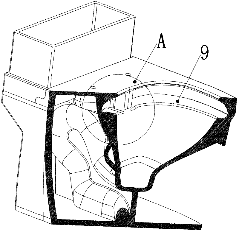
[0053] Comparative reference figure 1 , Figure 12 The difference between the second embodiment and the first embodiment lies in the end structure of the drainage channel 5 at the upper rear part of the bedpan 4. In the first embodiment, the upper end of the drainage channel 5 at the upper rear part of the bedpan 4 has two side end surfaces 7 and two oblique side end faces 6, the water spout 8 is on the two side end faces 7, and the water diversion ditch 12 is between the side end face 7 oblique side end faces 6 and the water inlet end 10 of the water diversion step 9; and in this specific embodiment two Among them, the drainage channel 5 has only two inclined side end faces 6 at the end of the upper rear part of the bedpan 4, the water spout 8 is on the two inclined side end faces 6, and the water diversion ditch 12 is on the inclined side end face 6 and the water inlet end 10 of the water diversion step 9. In between, the remaining parts are exactly the same as those in the...

specific Embodiment approach 3

[0054] Comparative reference figure 1 , Figure 13 The difference between the third embodiment and the first embodiment also lies in the end structure of the drainage channel 5 at the upper rear part of the bedpan 4. In the first embodiment, the upper end of the drainage channel 5 at the upper rear part of the bedpan 4 has two sides The end face 7 and the two oblique side end faces 6, the water spout 8 is on the two side end faces 7, and the water diversion ditch 12 is between the side end face 7 oblique side end face 6 and the water inlet end 10 of the water diversion step 9; and in this specific embodiment In the third, the drainage channel 5 has only two side end faces 7 at the end of the upper rear part of the bedpan 4, the water spout 8 is on the two side end faces 7, and the water diversion ditch 12 is between the side end faces 7 and the water inlet end 10 of the water diversion step 9 , and the rest are exactly the same as those in the first embodiment, and will not b...


PUM


Abstract

The invention relates to a siphon pedestal pan without a water ring. The pedestal pan comprises a water tank, a bedpan, a water discharge channel, a siphon blow-off pipeline and a water-saving device for injecting water into the bottom of the bedpan of the pedestal pan by using an external water source such as tap water, wherein the water discharge channel is communicated with a water discharge port of the water tank and the inner upper part of the bedpan; one end of the water discharge channel is positioned below the water discharge port of the water tank, and the other end of the water discharge channel is positioned on the rear upper part, which is close to the water tank, of the bedpan; the water discharge channel is provided with a water injection port at the end of the rear upper part of the bedpan and is communicated with the inner upper part of the bedpan only through the water injection port; the inner upper part of the bedpan is provided with two water diversion steps; each water diversion step is provided with a water inlet end; a water diversion ditch is arranged between the water injection port and the water inlet end of the water diversion step on the same side; a water inlet in the water-saving device is connected with the external water source such as the tap water; an injection boost port is connected to an injection boost hole at the bottom of the bedpan; and when water in the water tank is discharged, water injected from the injection boost port pushes the water which is discharged from the water tank and flows into the bottom of the bedpan and dirt.

Description

technical field [0001] The present invention relates to a toilet, in particular to a water-free siphon type which uses the water in the water tank to clean the inside of the toilet, and uses an external water source or tap water to pass through a water-saving device to push the water discharged from the water tank to the bottom of the toilet. toilet. Background technique [0002] There is a water circle on the bedpan of the existing common toilet, and the water circle is used as a water flow channel, and the water discharged from the water tank flows into the water circle and then flows into the bedpan through the small water holes in the lower part of the water circle, so as to achieve cleaning. The purpose of the bedpan under the water circle; when the water tank is drained, the water flow will have a certain impact on the inside of the water circle, but the impact of the water flow from the small water hole at the bottom of the water circle on the bedpan is relatively sma...

Claims


Application Information

Patent Timeline
IPC IPC(8): E03D11/02E03D1/38
Inventor 虞吉伟
Owner GUANGDONG HEGII SANITARY WARES CO LTD
Why Eureka
Try Eureka