Light bar as well as method and mould for manufacturing light bar

A technology for light bars and molds, which is applied to lighting and heating equipment, parts of lighting devices, semiconductor devices of light-emitting elements, etc., can solve the problem of not providing optical design and so on

Inactive Publication Date: 2012-04-04
OSRAM GMBH
View PDF5 Cites 1 Cited by
  • Summary
  • Abstract
  • Description
  • Claims
  • Application Information

AI Technical Summary

Problems solved by technology

The light bars obtained by the above three processing methods do not provide additional optical designs other than illuminants (usually LEDs), so the adjustment of light distribution is limited
In addition, the entire light bar does not involve the design of the mechanical structure, which is used for installing the light bar

Method used


Image

  • Light bar as well as method and mould for manufacturing light bar
  • Light bar as well as method and mould for manufacturing light bar
  • Light bar as well as method and mould for manufacturing light bar

Examples


Embodiment Construction

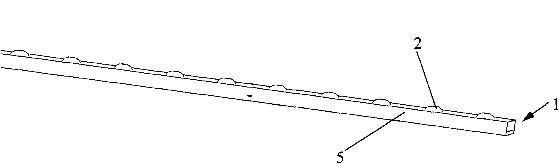
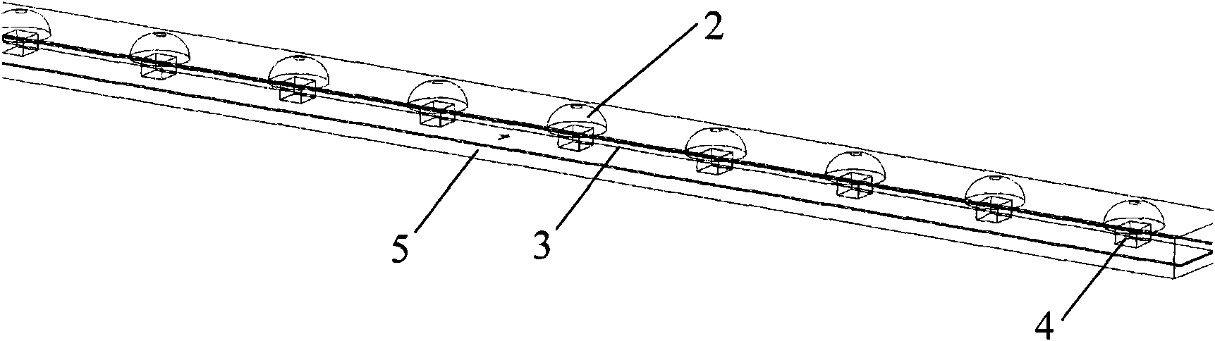
[0019] figure 1 The light bar 1 according to the invention is shown viewed from the side where the lens 2 is located. The light bar 1 includes a plurality of lenses protruding from the casing 5 distributed at intervals. The lens 2 and the housing 5 are integrally formed. The two can be made of one of PU glue and silicone. The position of the lens 2 on the outer surface is related to the LED lamp 4 on the circuit board 3 arranged in the casing 5 (an embodiment of the illuminant, image 3 The positions shown in ) are in one-to-one correspondence. This ensures that the light of the LED lamp 4 can emerge from the lens 2 and be optically adjusted, especially the light distribution.

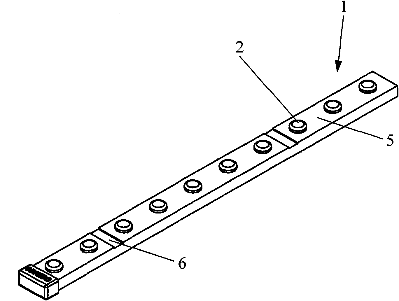
[0020] figure 2 An enlarged view of a lens and mounting part according to the present invention is shown. From the above, it can be seen clearly that a plurality of lenses 2 and a plurality of installation parts 6 disposed on the casing 5 are arranged at intervals, and the plurality of lenses 2 ...


PUM


Abstract

The invention relates to a method for manufacturing a light bar. The method for manufacturing the light bar (1) is characterized by comprising the following steps of: (a) providing a mould (7) with a cavity (8), wherein a plurality of lentiform concave holes (9) spaced at certain intervals are formed on the bottom of the cavity (8); (b) placing a circuit board (3) with a plurality of light emitting bodies (4) in the cavity (8), and keeping a certain distance between the circuit board (3) and the bottom of the cavity (8), wherein the lentiform concave holes (9) correspond to the positions of the light emitting bodies (4); (c) pouring a potting adhesive into the cavity (8) so that the entire cavity (8) is filled with potting adhesive; and (d) curing the potting adhesive. The invention also relates to a corresponding light bar. According to the method provided by the invention, the adjustment of optical properties especially light distribution of the light bar can be realized in a low cost and high efficiency manner.

Description

technical field [0001] The invention relates to a light bar, a method and a mold for manufacturing the light bar. Background technique [0002] Light bars are widely used in billboards, lighting signs, etc. The light bar generally includes that since the light bar is used in an outdoor environment, it is necessary to ensure its waterproof and dustproof properties. In the prior art, the following methods are usually used to produce light bars. One method is to firstly provide a U-shaped bottom plate, place a circuit board on which a plurality of illuminants are installed into the bottom plate, and then coat a transparent sealing material from above to encapsulate the circuit board. One method is to firstly provide a tubular casing with an end side opening, place a circuit board on which a plurality of illuminants are installed into the tubular transparent casing, and then fill the filling material from the end side opening. into the housing to encapsulate the circuit board...

Claims


Application Information

Patent Timeline
Patent Type & Authority Applications(China)
IPC IPC(8): F21S2/00F21V19/00F21V31/00F21V17/00
CPCF21V5/04F21S4/008F21Y2101/02F21V31/04F21S4/28F21Y2115/10
Inventor 范华建叶泽生罗亚斌杨灿邦
Owner OSRAM GMBH
Why Eureka
Try Eureka