
Connector for memory card

A memory card and connector technology, which is applied in the connection, the parts of the connection device, the device to prevent wrong connection, etc. The effect of reliable backoff

Active Publication Date: 2012-04-04
SMK CO LTD
View PDF6 Cites 0 Cited by
  • Summary
  • Abstract
  • Description
  • Claims
  • Application Information

AI Technical Summary

Problems solved by technology

[0006] On the other hand, in order to shield the contacts 102 and the memory card 10, the card receiving portion 103 is often covered by a cover 104 made of an elastic material such as a metal plate. 104 bends over the mis-insertion prevention protrusion 101, and may not be able to perform the mis-insertion prevention function
[0007] Moreover, since the mis-insertion prevention protrusion 101 needs to be arranged in the groove 11 not in contact with the memory card 10 behind the contact 102 in contact with the conductive sheet 12a, it cannot obtain a sufficient thickness for its insertion direction. Insufficient strength, so the memory card 10 inserted in an incorrect posture abuts against it and is easily damaged
[0008] In addition, it is necessary to form the tiny protrusions 101 with high precision on the inner surface of the housing constituting the card housing portion 103, and the mold structure for manufacturing the housing becomes complicated, requiring strict manufacturing precision.

Method used


Image

  • Connector for memory card
  • Connector for memory card
  • Connector for memory card

Examples


Embodiment Construction

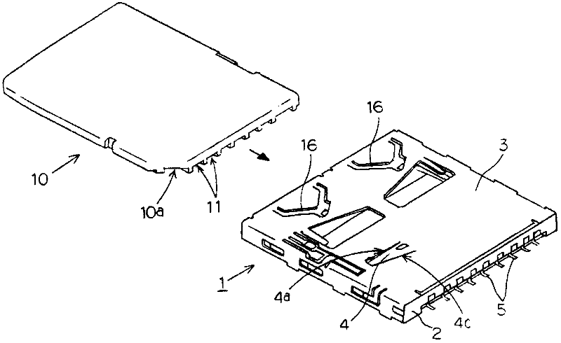
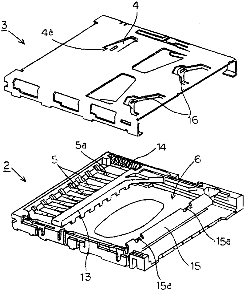
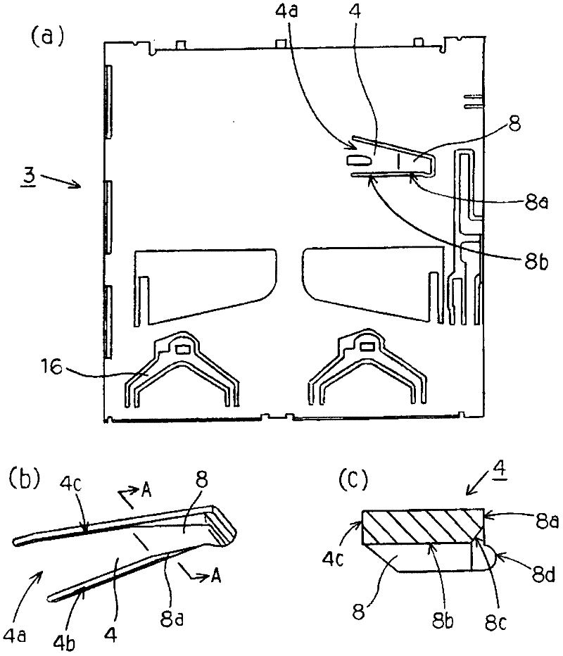
[0042] Next, use Figure 1 to Figure 8 A memory card connector 1 according to an embodiment of the present invention will be described. For the description of the memory card connector 1, the figure 2 The cover 3 side is the upper side, the housing 2 side is the lower side, and the image 3 The up-down direction in (a) is the front-back direction, and the left-right direction is the left-right direction, and it demonstrates. like figure 2 As shown, the memory card connector 1 includes: a housing 2, which is composed of a U-shaped frame portion along the periphery except the rear and forms a concave portion inside; and is assembled along the upper surface of the housing 2 The conductive metal cover 3 covers the concave portion of the casing 2 from above, thereby forming a card storage portion 6 for storing the memory card 10 therebetween.

[0043] The case 2 is molded from an insulating synthetic resin, and when the case 2 is molded, a plurality of contacts 5 are integral...


PUM


Abstract

The invention provides a memory card connector which needs no processing of the housing, has a simple structure and can prevent a memory card from being inserted in a wrong gesture. A leaf spring supported by a cantilever is integrally formed on a cover. At least a mis-insertion preventing plate part at the free end of the leaf spring is inclined towards the lower part of the cover. The rear side face and the card inserting direction face a card receiving part in an orthogonal way and pass through the moving track of the inclined face of a memory card inserted in the card receiving part. The inclined face of the memory card inserted in a normal gesture abuts on the lower part of the rear side surface. The mis-insertion preventing plate is pushed. The flat face of the memory card inserted in a wrong gesture abuts on the rear side surface. Then the mis-insertion preventing plate is limited.

Description

technical field [0001] The present invention relates to a memory card connector for connecting a memory card housed in a card storage unit to an electronic device, and more specifically, to a memory card connector provided with a wrong insertion prevention mechanism that restricts the insertion of a memory card that is to be inserted in an incorrect posture. Connector for memory card. Background technique [0002] Before, such as Figure 8 As shown, in a memory card 10 such as a large SD card, an inclined surface 10a is formed on the front side in the insertion direction into the card storage portion. like Figure 11 As shown, in the memory card connector 100 connected to the memory card 10 formed with the inclined surface 10a, a mis-insertion prevention protrusion 101 and the like are formed at the portion notched by the inclined surface 10a of the memory card 10, thereby eliminating the need for previous Insertion of the memory card 10 inserted into the card storage port...

Claims


Application Information

Patent Timeline
Patent Type & Authority Applications(China)
IPC IPC(8): H01R13/502H01R13/64H01R12/71
Inventor 江尻孝一郎
Owner SMK CO LTD
Learn More