Engine room chassis and mounting method thereof

A machine room and chassis technology, applied in the field of machine room chassis and its installation, can solve the problems of not meeting sufficient safety requirements and rigidity requirements, etc., achieve flexible and adjustable size, prevent excessive deformation, and prevent large-scale free vibration Effect

Pending Publication Date: 2019-11-01
SHANGHAI ZHENHUA HEAVY IND
View PDF0 Cites 0 Cited by
  • Summary
  • Abstract
  • Description
  • Claims
  • Application Information

AI Technical Summary

Problems solved by technology

After the actual wharf conditions and the actual needs of users have many restrictions on the overall steel structure of the quay bridge, the conventional metal structure support of the chassis of the machine room cannot meet sufficient safety requirements, or cannot meet specific rigidity requirements

Method used


Image

  • Engine room chassis and mounting method thereof
  • Engine room chassis and mounting method thereof
  • Engine room chassis and mounting method thereof

Examples


no. 1 approach

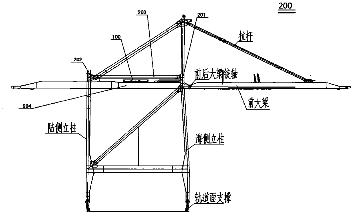
[0054] The first embodiment is mainly applicable to the case where the main support structure 10 is located below the horizontal connecting rod 203 of the quay crane 200 along the direction of gravity, and is suitable for completing installation at low altitudes, avoiding high-altitude operations.

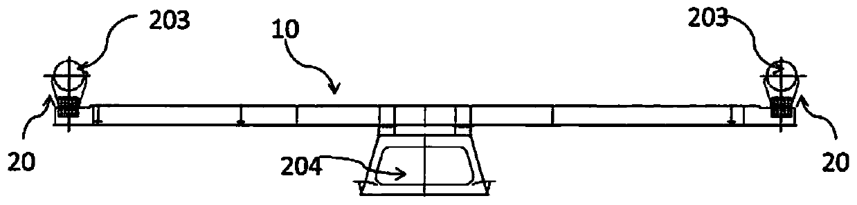
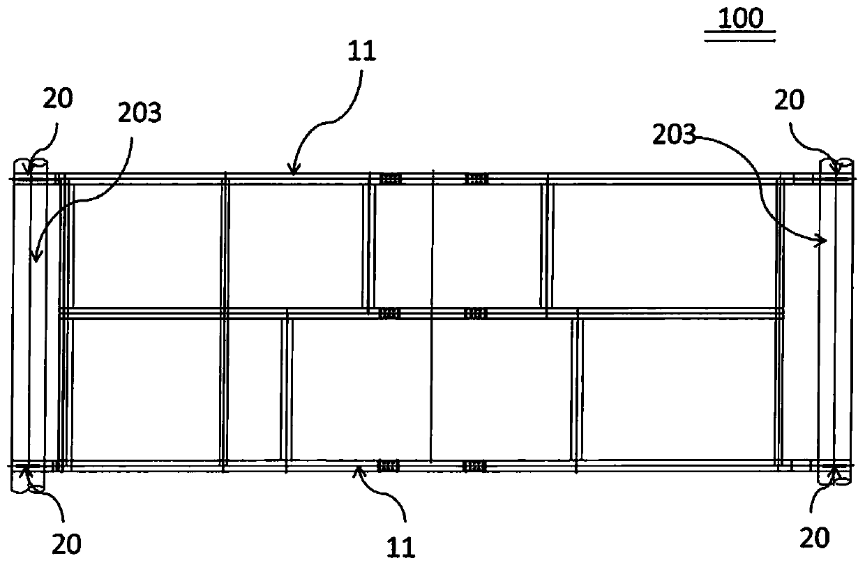
[0055] Such as Figure 3a~3c As shown, the first part 21 is T-shaped steel, the flange plate of the first part 21 is connected with the transverse main beam, and the web of the first part 21 is connected with the third part 23; as Figure 4a , 4b As shown, the second component 22 is a sheet, and the contact end of the second component 22 and the horizontal connecting rod 203 partially surrounds the horizontal connecting rod 203; Figure 5a , 5b As shown, the third part 23 is a double-layer sheet, so as to clamp the first part 21 and the second part 22, that is, the first part 21 and the second part 22 of the auxiliary support 20 after installation are all clamped by the second pa...


PUM


Abstract

The invention aims at providing an engine room chassis. The engine room chassis comprises a main supporting structure and an auxiliary supporting part. The engine room chassis is used for supporting an engine room of a shore bridge. The main supporting structure comprises a transverse main beam, a longitudinal main beam and other function parts, the auxiliary supporting part is arranged on the outmost end of the transverse main beam, and comprises a first part, a second part and a third part, the first part is connected with the transverse main beam, the second part is connected with a horizontal connecting rod of the shore bridge, and the third part is used for connecting the first part with the second part. According to the technical scheme, an original cantilever beam is changed into astructure with weak supporting, too large deforming of the outmost end of the chassis and large bending moment of the main beam can be prevented, and safety of the engine room chassis during work canbe improved. The invention provides a mounting method of the engine room chassis. Parts are convenient to manufacture, production difficulty and production cost are greatly reduced, whole mounting isconvenient, and the size is flexible and adjustable.

Description

technical field [0001] The invention relates to the field of quay bridges, in particular to a machine room chassis and an installation method thereof. Background technique [0002] Quayside container cranes (referred to as: quayside cranes) have many projects and various forms. According to the actual data of the wharf and the actual requirements of users, the quay crane often needs some new ideas and designs, especially the design of the metal structure of the quay crane. After the actual wharf conditions and the actual needs of users have imposed many restrictions on the overall steel structure of the quay bridge, the conventional metal structure support of the chassis of the machine room cannot meet sufficient safety requirements, or cannot meet specific rigidity requirements. Contents of the invention [0003] In order to solve the above problems, one of the objects of the present invention is to provide a machine room chassis, which is mainly aimed at the situation t...

Claims


Application Information

Patent Timeline
Patent Type & Authority Applications(China)
IPC IPC(8): B66C13/52F16M7/00
CPCB66C13/52F16M7/00
Inventor 罗磊汪杰曾鹏李义明
Owner SHANGHAI ZHENHUA HEAVY IND
Why Eureka
Try Eureka