Crane and its displacement device

A displacement device and frame technology, which is applied in the field of displacement devices and cranes, can solve the problems affecting the working efficiency of the equipment and the staff's field of vision is not wide enough to achieve the effect of increasing position changes, expanding the field of vision, and realizing up and down displacement

Inactive Publication Date: 2012-04-11
XUZHOU HEAVY MASCH CO LTD
View PDF7 Cites 7 Cited by
  • Summary
  • Abstract
  • Description
  • Claims
  • Application Information

AI Technical Summary

Problems solved by technology

[0008] However, in the scheme provided by the above-mentioned prior art, because the position of the control room is usually high, it brings great inconvenience to the staff entering and leaving the control room, which affects the working efficiency of the equipment; and, in some cases, the staff's field of vision is still not wide enough

Method used


Image

  • Crane and its displacement device
  • Crane and its displacement device
  • Crane and its displacement device

Examples


Embodiment Construction

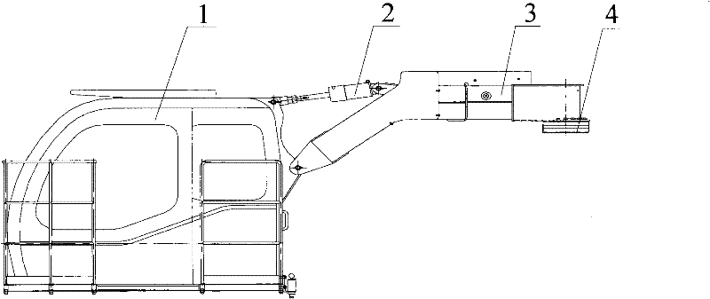
[0033] The core of the present invention is to provide a displacement device, which can realize the up and down movement of the control room, which is convenient for personnel to enter and exit the control room, and at the same time increases the changing position of the control room and expands the staff's field of vision. Another core of the present invention is to provide a crane including the above-mentioned displacement device.

[0034] In order to enable those skilled in the art to better understand the solution of the present invention, the present invention will be further described in detail below in conjunction with the accompanying drawings and specific embodiments.

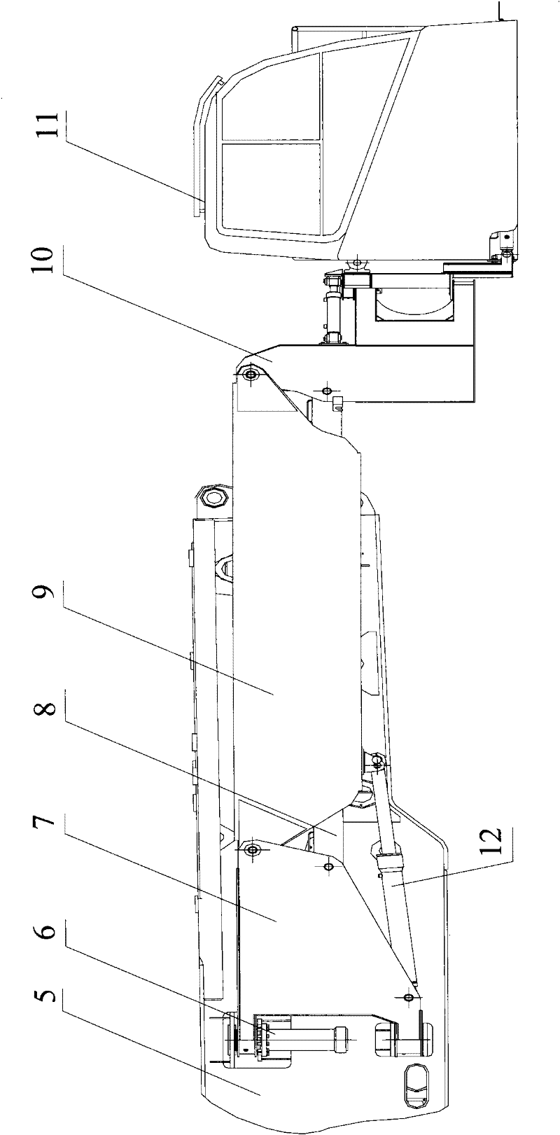
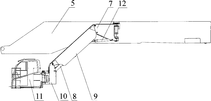
[0035] Please refer to figure 2 and image 3 , figure 2 It is a schematic diagram of the connection relationship between the displacement device and the control room in a specific embodiment provided by the present invention, image 3 for figure 2 Schematic diagram of the position state after th...


PUM


Abstract

The invention provides a displacement device disposed between the rotary table and control room of an engineering machine. The displacement device comprises a four-bar linkage and a first transmission mechanism. The four-bar linkage consists of a frame body, an upper side link body, a connecting rod body and a lower side link body that are hinged in order. The first transmission mechanism is disposed between the frame body and the rotary table, and used for driving the four-bar linkage to rotate relative to the rotary table horizontally. A first oil cylinder is positioned between the frame body and one of the upper side link body and the lower side link body. The connecting rod body is in connection with the control room. The displacement device of the invention can be convenient for staff to get in and out of the control room and can broaden the horizon of staff. In addition, the invention also provides a crane with the above displacement device.

Description

technical field [0001] The invention relates to the technical field of construction machinery displacement, in particular, a displacement device is designed. In addition, the present invention also relates to the field of hoisting equipment, in particular to a crane. Background technique [0002] With the rapid development of the economy, large-scale projects continue to increase. The scale of construction projects in wind power, thermal power, nuclear power and other energy industries continues to expand, hoisting projects are developing in the direction of large-scale and large-scale, and the application range of cranes is also becoming wider and wider. [0003] The control room of the crane is the command center to realize the work of the crane and the link of man-machine connection. [0004] The control room is installed on the turntable of the crane, and the position of the control room needs to be changed according to the different requirements of the lifting state a...

Claims


Application Information

Patent Timeline
IPC IPC(8): B66C13/54
Inventor 单增海贾体锋张正得王志陈志芳李长青
Owner XUZHOU HEAVY MASCH CO LTD
Why Eureka
Try Eureka