Overhead line insulator decontamination device
What is Al technical title?
Al technical title is built by PatSnap Al team. It summarizes the technical point description of the patent document.
An insulator and cleaning technology, applied in overhead line/cable equipment, chemical instruments and methods, cleaning methods and utensils, etc., can solve problems such as low work efficiency, hidden dangers to personal safety, and inability to work online, and achieve low production costs. , High practicability, the effect of preventing water pipe entanglement
Active Publication Date: 2018-08-17
HEBEI UNIV OF TECH
View PDF2 Cites 0 Cited by
Summary
Abstract
Description
Claims
Application Information
AI Technical Summary
This helps you quickly interpret patents by identifying the three key elements:
Problems solved by technology
Method used
Benefits of technology
Problems solved by technology
However, for the staff, this method has personal safety hazards
[0003] The Chinese patent with the application number 201510334199.6 discloses an automatic cleaning system for insulators. The system places the removed insulators on a rotating tray device, and transports the insulators to the cleaning mechanism for cleaning through a mechanical arm. The entire project has a high degree of automation, but The process is complicated, the insulator needs to be removed, and it cannot work online
[0004] The Chinese patent No. 201410404083.0 discloses an electric cleaning device for insulators. The electric cleaning head in the device is connected to the cleaning joint above the water tank, and an electric cleaning arm is arranged above the cleaning joint seat. The stepping motor is used to drive the electric cleaning device. The cleaning arm rotates, the disadvantage is that the cleaning work of the device is only completed by the rotation of a single cleaning head, and the work efficiency is not high
Method used
Image
Click on the blue label to locate the original text in one second.
Reading with bidirectional positioning of images and text.
Examples
Embodiment Construction
[0025] The present invention will be described in further detail below in conjunction with the embodiments and accompanying drawings, but this should not be used as a limitation to the protection scope of the claims of the present application.
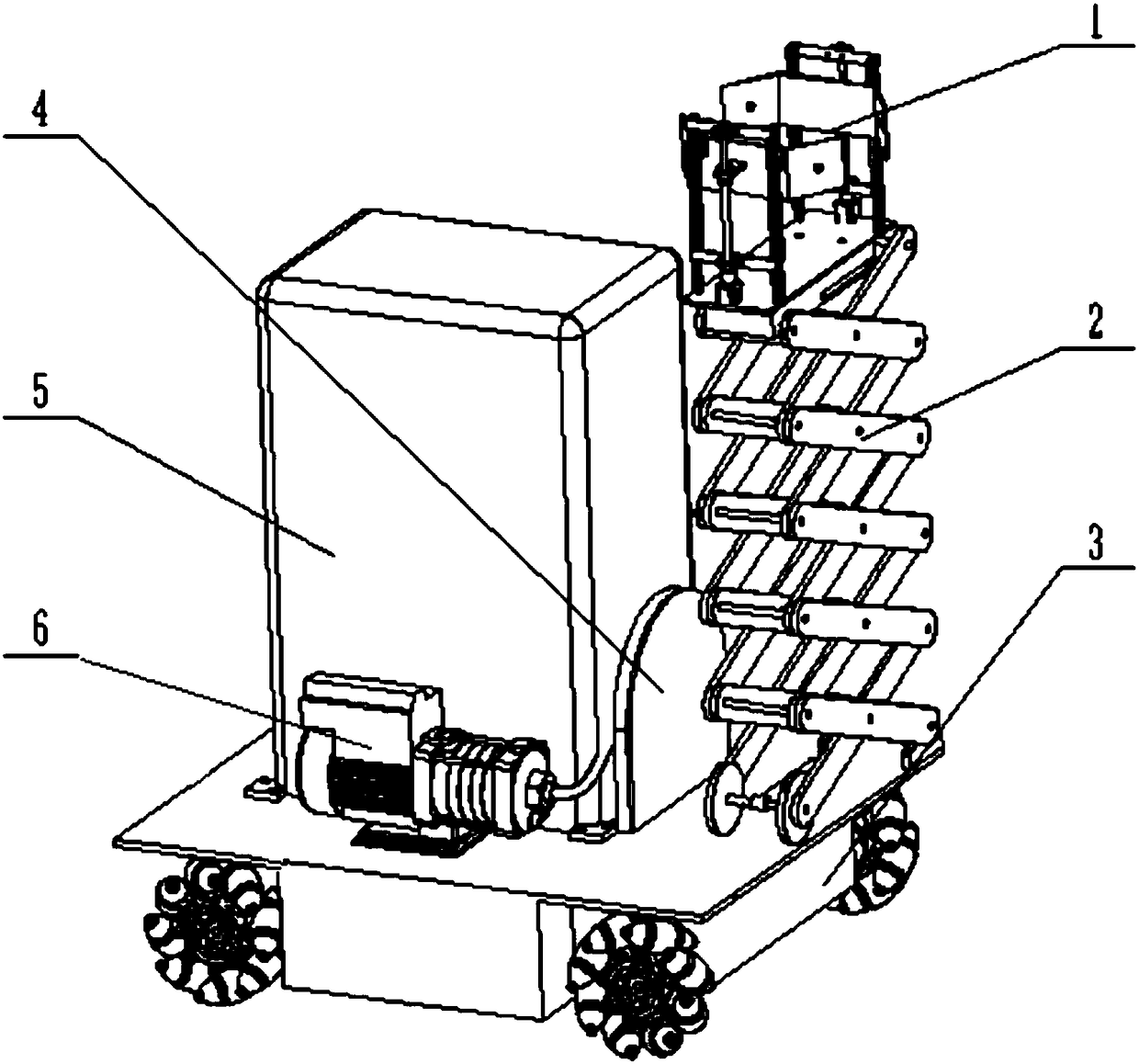
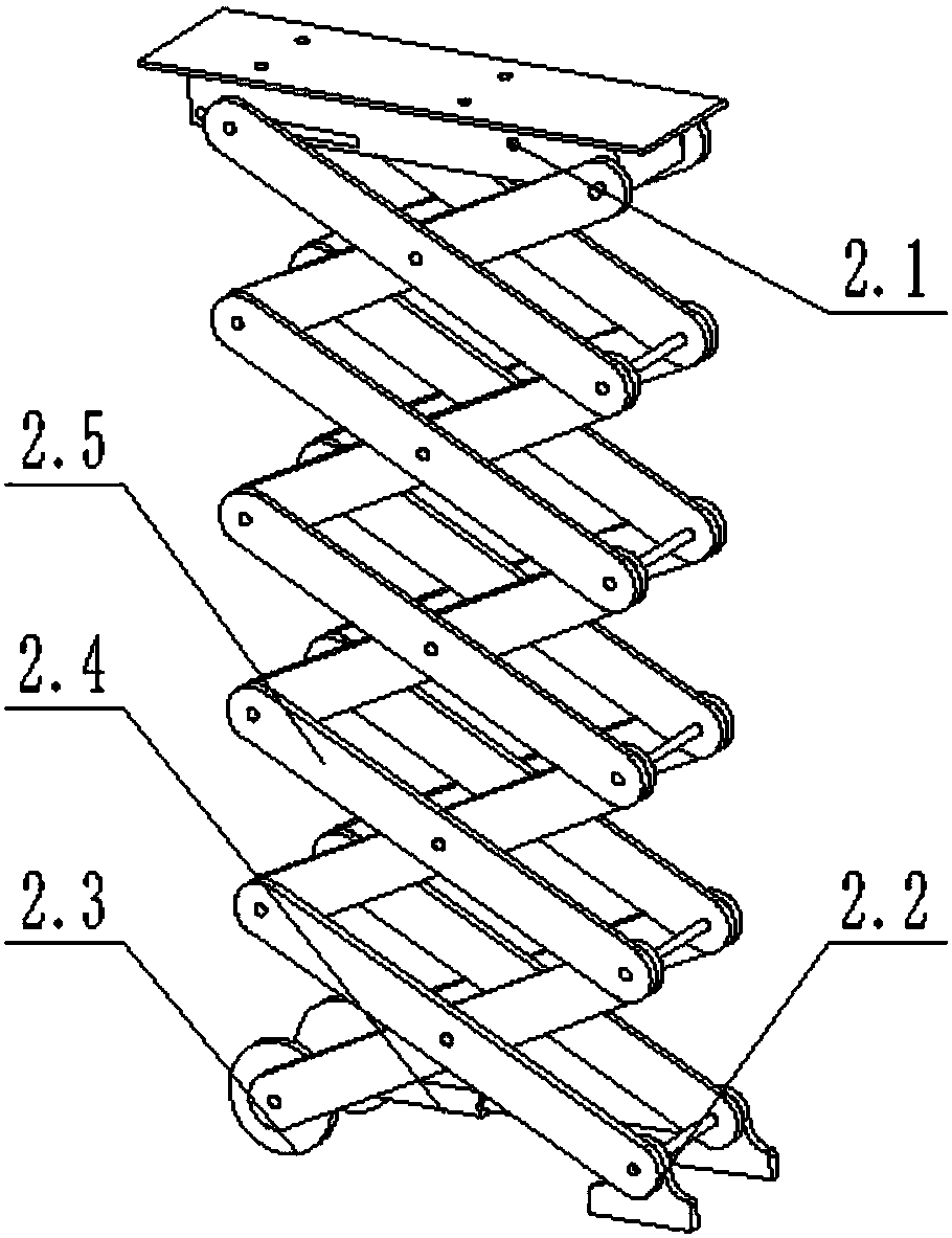
[0026] The overhead wire insulator decontamination device of the present invention (abbreviation device, see Figure 1-6 ) includes a cleaning module 1, a lifting module 2, a walking module 3, a water pipe box 4, a water tank 5 and a water pump 6; Fixed on the walking module 3, the water pipe box 4 is connected with the water tank 5 through the water pump 6;
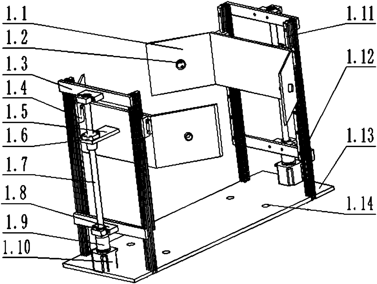
[0027] The cleaning module 1 (see Figure 2-3 ) includes a cleaning arm 1.1, a nozzle 1.2, a slider 1.4, a screw nut mechanism, a guide rail 1.11, a guide rail frame 1.12 and a workbench 1.13; the workbench 1.13 is provided with a workbench water outlet 1.14, and the outside of the workbench water outlet is provided with Guide rail bracket 1.12, the guide rail 1.11 is fixed on ...
PUM
Abstract
The invention relates to a cleaning device for insulators of electric lines. The cleaning device is characterized by comprising a cleaning module, a lifting module, a walking module, a water pipe box, a water tank and a water pump, wherein the cleaning module is fixed to the walking module by virtue of the lifting module, the water pipe box, the water tank and the water pump are all fixed to the walking module, and the water pipe box is connected with the water tank by virtue of the water pump; the cleaning module comprises a cleaning arm, a nozzle, a sliding block, a screw-nut mechanism, a guide rail, guide rail brackets and a workbench; a workbench water outlet is formed in the workbench, the guide rail brackets are arranged on the outer side of the workbench water outlet, the guide rail is fixed to the guide rail brackets by virtue of screws, a connecting frame is horizontally connected between the two adjacent guide rail brackets, the screw-nut mechanism is fixed to the outer side of the middle of the connecting frame along a vertical direction, and the screw-nut mechanism comprises a screw connecting plate, a screw nut, a screw, bearing seats, a coupling and a stepping motor; the stepping motor is connected with screw by virtue of the coupling, and the bearing seats sleeve both ends of the screw.
Description
technical field [0001] The invention relates to the technical field of power line maintenance, in particular to an overhead line insulator decontamination device. Background technique [0002] Insulators are essential in power lines. They play a role in preventing current from flowing between conductors with different potentials or returning to the ground. They can also support the conductors and withstand the corresponding mechanical stress. Insulators operating outdoors will be polluted by dust, smoke and industrial emissions, forming a dirty layer on the porcelain surface. The surface flashover of polluted insulators under the action of voltage is also called pollution flashover. In a dry state, insulators are not greatly affected by surface pollution flashover, but in climatic conditions such as fog, dew, snow, drizzle, etc., the pollution layer on the surface of the insulator is damp, and its flashover voltage is greatly reduced, which will lead to pollution flashover ...
Claims
Application Information
Patent Timeline
Application Date:The date an application was filed.
Publication Date:The date a patent or application was officially published.
First Publication Date:The earliest publication date of a patent with the same application number.
Issue Date:Publication date of the patent grant document.
PCT Entry Date:The Entry date of PCT National Phase.
Estimated Expiry Date:The statutory expiry date of a patent right according to the Patent Law, and it is the longest term of protection that the patent right can achieve without the termination of the patent right due to other reasons(Term extension factor has been taken into account ).
Invalid Date:Actual expiry date is based on effective date or publication date of legal transaction data of invalid patent.