Integral structure of a turn-milling complex machining center

A compound machining center and overall structure technology, which is applied in metal processing, metal processing equipment, manufacturing tools, etc., can solve problems such as lack of precision, and achieve the effects of improving efficiency, smooth chip removal, and high precision retention

Active Publication Date: 2009-08-26
通用技术集团沈阳机床有限责任公司
View PDF0 Cites 31 Cited by
  • Summary
  • Abstract
  • Description
  • Claims
  • Application Information

AI Technical Summary

Problems solved by technology

Even the machinery and equipment manufacturing industry has no good solutions to the above problems.

Method used


Image

  • Integral structure of a turn-milling complex machining center
  • Integral structure of a turn-milling complex machining center
  • Integral structure of a turn-milling complex machining center

Examples


Embodiment Construction

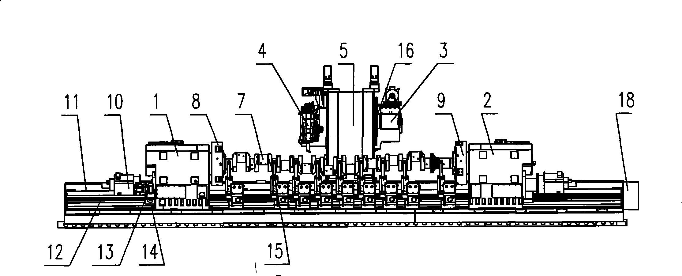
[0018] The overall structure of the turning-milling compound machining center is a special structure designed for machining the crankshaft of a medium-speed marine machine, and realizes the machining of each part of the crankshaft main journal and connecting rod journal before grinding on one machine tool. It is characterized in that it consists of the following five parts. :

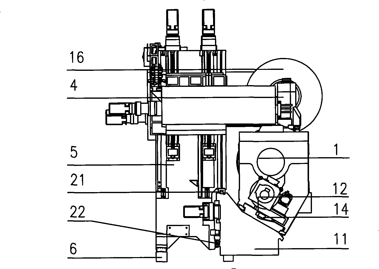
[0019] 1. Single column, double side hanging feed mechanism

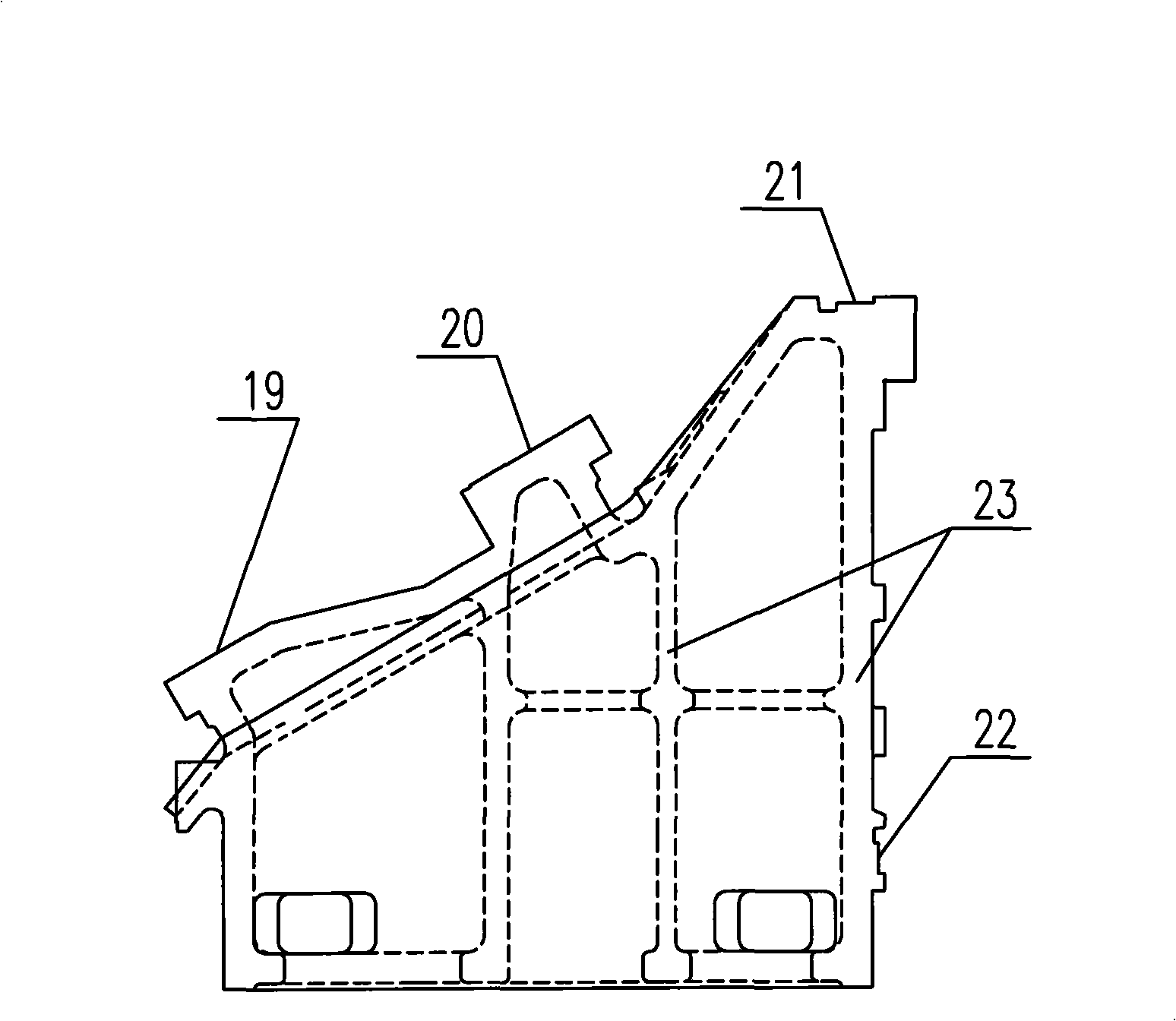
[0020] Such as figure 1 , figure 2 As shown, the single column 5 is located at the rear side of the bed, its lower front end is located in the rolling guide rails 21, 22 on the bed, and the rear end runs in the ground auxiliary guide rail 6. The stroke of the single column 5 is determined by the length of the workpiece. The single column 5 The left and right feeding mechanisms 4 and 3 are respectively hung on both sides, and the left feeding mechanism 4 is equipped with a B-axis tool holder device with three-point cloth knives. Knife and ...


PUM


Abstract

An integral structure of a turn-milling complex machining center is disclosed, characterized by a single post and feeding boxes hung at two sides. The left-suspending feeding box is provided with a B-axis cutter holder device with cutters at three locations. The B-axis cutter holder device is used for the working procedures for crank machining like turning, milling, boring, deep-hole drilling, threading and the like. The right-suspending feeding box can be provided with a large-scale milling cutter disc for external milling machining of the crank shaft. Two spindle boxes have two Cf-axis structures, the two spindle boxes are movable along a Z-axis on the machine body, and the tip of the right spindle box is stretchable. The machine is fitted with a plurality of hydraulic self-centering center rests that have high precision retentivity. A guide rail on the machine body forms an angle of inclination of 30 degrees with a horizontal plane, and the plane of the machine body is completely ground to ensure the absence of scraps and dead corners. The entire machine is fully protected. An inner cavity of the guide rail for the operation of the single post of the machine body is supported by double ribs, and two sets of corners remain stressed all the time in the process of the operation of the post. A front support bearing of the spindle employs an imported large-diameter double-column cylindrical roller bearing. The invention solves three problems and the machining for parts of a main journal and a connecting journal of the crank prior to grinding can be completed by one-time mounting on a machine, thus realizing high-precision and high efficient machining for the crank shaft of a medium speed machine for ships; in addition, the invention bears heavy load and is fully-protected.

Description

technical field [0001] The invention relates to mechanical manufacturing equipment and the overall structural layout of a turning-milling compound machining center Background technique [0002] The crankshaft is known as the "heart" of the 10,000-ton wheel "heart" (engine), but China's shipbuilding industry has been lacking this "Chinese heart" for decades, and Chinese marine diesel engine manufacturers "ships wait for machines, machines wait for shafts" The situation has not been alleviated for several years, resulting in longer and longer delivery periods for Chinese shipbuilding companies, and has become a bottleneck restricting the development of China's shipbuilding industry. The material of the medium and low speed crankshaft for marine is cast iron or forged steel, and the shape is a long axis with multiple cranks. Since the rotary axis of the crank, that is, the connecting rod journal and the main journal are not concentric, the rotation diameter of the crank around ...

Claims


Application Information

Patent Timeline
Patent Type & Authority Applications(China)
IPC IPC(8): B23Q39/02
Inventor 李宪凯郭秀英李晓岩姜庆凯李晓峰白紫山盖立亚金明刚何峰刘春莉徐书友
Owner 通用技术集团沈阳机床有限责任公司
Why Eureka
Try Eureka