Rotary constant-speed water decanter

A decanter and rotary technology, applied in the field of rotary uniform decanters, can solve problems such as uneven decanting speed

Inactive Publication Date: 2012-04-11
姚茂红
View PDF2 Cites 2 Cited by
  • Summary
  • Abstract
  • Description
  • Claims
  • Application Information

AI Technical Summary

Problems solved by technology

When the decanting tank descends, the decanting tank does not descend at a uniform speed because the transmission screw advances at a constant speed, and the decanting speed is not uniform.

Method used


Image

  • Rotary constant-speed water decanter
  • Rotary constant-speed water decanter
  • Rotary constant-speed water decanter

Examples


Embodiment Construction

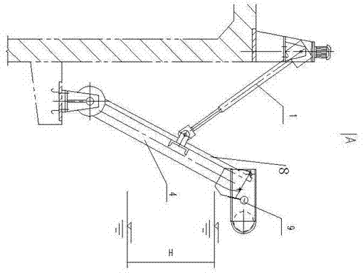
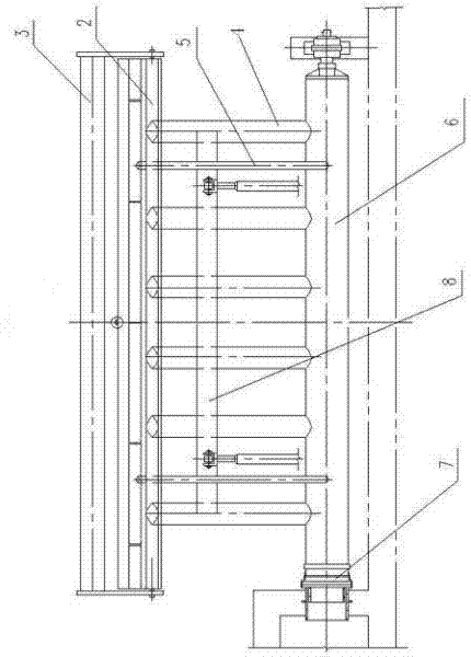
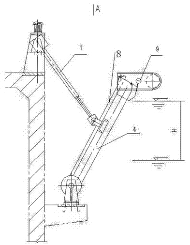
[0008] A rotary constant speed decanter, comprising a transmission device 1, a decanting tank 2, a skimming tank 3, a drainage branch pipe 4, an exhaust pipe 5, a main drain pipe 6, a slewing bearing 7, and the skimming tank 3 is connected to the decanting tank 2, The decanting tank 2, drainage branch pipe 4 and exhaust pipe 5 are fixed on the drainage main pipe 6, one end of the drainage main pipe 6 is inserted into the slewing bearing 7, one end of the transmission device 1 is hinged with the connecting rod 8 of the drainage branch pipe 4, and the other end is fixed by a trunnion On the frame, the transmission device 1 communicates with the controller signal in the control box, a liquid level probe 9 is arranged above the weir of the decanting tank 2, and a frequency converter is added in the control box. The liquid level probe 9, frequency converter and transmission Device 1 signal connection.


PUM


Abstract

The invention relates to a rotary constant-speed water decanter, and belongs to the technical field of wastewater treatment machinery. The rotary constant-speed water decanter comprises a transmission device, a water decanting tank, a scumming drum, a water discharge branch pipe, an air exhaust pipe, a water discharge main pipe and a slewing bearing, wherein the scumming drum is connected with the water decanting tank; the water decanting tank, the water discharge branch pipe and the air exhaust pipe are fixed on the water discharge main pipe; one end of the water discharge main pipe is inserted into the slewing bearing; one end of the transmission device is hinged with a connection rod of the water discharge branch pipe, and the other end of the transmission device is fixed on a frame through an trunnion; the transmission device is in signal communication with a controller in a control box; a liquid level probe is arranged on the weir port of the water decanting tank; a frequency converter is arranged in the control box; and the liquid level probe and the frequency converter are in signal connection with the transmission device. The device provided by the invention has the advantages of reasonable and simple structure, easiness in production and manufacture, low cost, convenience in operation and use and reliability in operation, and can truly achieve constant-speed descending of the overflow weir port of the water decanting tank and constant-speed water decanting.

Description

technical field [0001] The invention relates to a rotary constant-velocity decanter for separating supernatant liquid in the sewage treatment process of the SBR method, and belongs to the technical field of sewage treatment machinery. Background technique [0002] At present, the rotary decanter is mainly composed of a transmission device, a decanting tank, a skimming cylinder, a drainage branch pipe, an exhaust pipe, a drainage main pipe, a slewing bearing, and a drainage branch pipe connecting rod. One end of the transmission device is hinged with the connecting rod of the drainage branch pipe, and the transmission screw moves in a straight line to push the decanting tank combination to move around the center of the main drainage pipe to realize the lifting movement of the decanting tank. The other end of the transmission device is fixed on the frame through the trunnion. The decanting tank swings up and down slightly, and the supernatant is decanted from the weir at a non...

Claims


Application Information

Patent Timeline
Patent Type & Authority Applications(China)
IPC IPC(8): C02F3/30C02F3/12
CPCY02W10/10
Inventor 姚茂红吴志强魏刚杰王为民
Owner 姚茂红
Why Eureka
Try Eureka